
CONTROL SYSTEMS ENGINEERING
7th Edition
ISBN: 2819770197050
Author: NISE
Publisher: WILEY
expand_more
expand_more
format_list_bulleted
Videos
Textbook Question
Chapter 4, Problem 69P
Figure P4.l6 shows the step response of an electric vehicle's
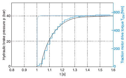
FIGURE P4.16 Step response of an electric vehicle's mechanical brake11
a. Find the transfer function of the system.
b. Use the values of the parameters for the transfer function obtained in Part a to find an expression for the brake pressure as a function of time.
c. Find the output in bars of the system 0.2 sec after the input is applied. Check your result against Figure P4.16.
Expert Solution & Answer
Want to see the full answer?
Check out a sample textbook solution
Students have asked these similar questions
Q1 The mass-damper-spring mechanical system is shown in Figure Q1, Mass slide
on a frictionless surface.
F(t)
y(t)
x(t)
K2
K1
M1
M2
Negligible friction
Figure Q1
Assume mass, M, = M2 = 1 kg, damping coefficient C = 1 Ns/m and spring
stiffness, K = 1 N/m. Both masses slide on a frictionless surface.
Develop the transfer function for this mechanical system.
Assume F(t) is a step force input and the displacement is x(t) obtain the transfer function for the system shown below. Assume all initial conditions are zero. F(t) = 5 N, m = 0.2 kg, c = 0.3 N-s/m, k1 = 5 N/m and k2 = 4 N/m. 3. Find the global stiffness matrix, displacement at nod
For the system shown in the figure. the system parameters, the length of the rod, l is
2 m, mass of the rigid rod, m is 7, and the stiffness of the
springs, k, is the last two digits of 57.
Derive the equation of motion,
b) Find the transfer function between
force input (F) and angular
displacement (θ) of the system
c) Find the step response of the
system, and show time-domain
characteristics of the system
d) Find the frequency response
function, and draw frequency
response graphs, and draw bode diagrams, show frequency-domain characteristics.
Chapter 4 Solutions
CONTROL SYSTEMS ENGINEERING
Ch. 4 - Prob. 1RQCh. 4 - What does the performance specification for a...Ch. 4 - Prob. 3RQCh. 4 - In a system with an input and an output, what...Ch. 4 - Prob. 5RQCh. 4 - Prob. 6RQCh. 4 - 7. What is the difference between the natural...Ch. 4 - Prob. 8RQCh. 4 - Prob. 9RQCh. 4 - Prob. 10RQ
Ch. 4 - List five specifications for a second-order...Ch. 4 - Prob. 12RQCh. 4 - What pole locations characterize (1) the...Ch. 4 - Prob. 14RQCh. 4 - How can you justify pole-zero cancellation?Ch. 4 - Prob. 16RQCh. 4 - 17. What is the relationship between , which...Ch. 4 - Name a major advantage of using time-domain...Ch. 4 - Prob. 19RQCh. 4 - What three pieces of information must be given in...Ch. 4 - 21. How can the poles of a system be found from...Ch. 4 - Prob. 1PCh. 4 - Prob. 2PCh. 4 - MATIAB ML 3. Plot the step responses for Problem 2...Ch. 4 - Find the capacitor voltage in the network shown in...Ch. 4 - For the system shown in Figure P4.3, (a) find an...Ch. 4 - Prob. 8PCh. 4 - MATLAB ML 9. Use MATLAB to find the poles of...Ch. 4 - Find the transfer function and poles of the system...Ch. 4 - MATLAB ML 11. Repeat Problem 10 using MATLAB....Ch. 4 - Write the general form of the capacitor voltage...Ch. 4 - Solve for x(t) in the system shown in Figure P4.5...Ch. 4 - Prob. 15PCh. 4 - Prob. 16PCh. 4 - Calculate the exact response of each system of...Ch. 4 - Prob. 18PCh. 4 - Prob. 19PCh. 4 - For each of the second-order systems that follow,...Ch. 4 - MATLAB ML 21. Repeat Problem 20 using MATLAB. Have...Ch. 4 - GUI Tool GUIT
22. Use MATLAB’s LTI Viewer and...Ch. 4 - Prob. 23PCh. 4 - Find the transfer function of a second-order...Ch. 4 - For the system shown in Figure P4.7, do the...Ch. 4 - For the system shown in Figure P4.8, a step torque...Ch. 4 - Prob. 28PCh. 4 - Prob. 29PCh. 4 - Prob. 30PCh. 4 - Prob. 31PCh. 4 - Prob. 32PCh. 4 - Prob. 33PCh. 4 - Prob. 34PCh. 4 - Prob. 35PCh. 4 - Prob. 36PCh. 4 - State Space SS 38. A system is represented by the...Ch. 4 - Prob. 39PCh. 4 - Prob. 40PCh. 4 - State Space SS 41. Given the following system...Ch. 4 - State Space SS 42. Solve the following state...Ch. 4 - Prob. 43PCh. 4 - Prob. 44PCh. 4 - Prob. 46PCh. 4 - Prob. 47PCh. 4 - Prob. 48PCh. 4 - Prob. 53PCh. 4 - Prob. 54PCh. 4 - A MOEMS (optical MEMS) is a MEMS (Micro...Ch. 4 - Prob. 56PCh. 4 - Prob. 59PCh. 4 - Prob. 60PCh. 4 - Prob. 61PCh. 4 - Prob. 63PCh. 4 - Prob. 67PCh. 4 - Figure P4.l6 shows the step response of an...Ch. 4 - Figure P4. I 7 shows the free-body diagrams for...Ch. 4 - Find an equation that relates 2% settling time to...Ch. 4 - Prob. 74PCh. 4 - Prob. 75PCh. 4 - 76. Find J and K in the rotational system shown in...Ch. 4 - Given the system shown in Figure P4.22, find the...Ch. 4 - Prob. 78PCh. 4 - Find M and K, shown in the system of Figure P4.24,...Ch. 4 - If vi(t) is a step voltage in the network shown in...Ch. 4 - Prob. 81PCh. 4 - Prob. 82PCh. 4 - For the circuit shown in Figure P4.26, find the...Ch. 4 - Prob. 84PCh. 4 - Prob. 86P
Knowledge Booster


Learn more about
Need a deep-dive on the concept behind this application? Look no further. Learn more about this topic, mechanical-engineering and related others by exploring similar questions and additional content below.Similar questions
- P4.7 A robot uses feedback to control the orientation of each joint axis. The load effect varies due to varying load objects and the extended position of the arm. The system will be deflected by the load carried in the gripper. Thus, the system may be represented by Figure P4.7 O, where the load torque is Ta (s) = D/s. Assume R(s) = 0 at the index position. (a) What is the effect of Ta(s) on Y(s)? (b) Determine the sensitivity of the closed loop to k2. (c) What is the steady-state error when R (s) = 1/s and Ta(s) = 0? Load disturbance T (s) R(s) Controller Y(s) Desired k2 Actual k1 joint angle joint angle s(TS + 1) kz + k4s Figure P4.7 Robot control system.arrow_forwardDerive transfer function for the following mechanical system: x(t) - Laplace transforms. f(t) M Spring K Damper B. Referencearrow_forward3. Consider the system shown below. The outputs of the system are the angular displacement of the upper gear (positive about the x-axis) and the Contact force between the upper and lower gear. Assume that the initial conditions for all state variables are zero and that the gears are massless. There are two inputs Ti(t) acting on the top gear and T₂(t) acting on the rightmost disk. If you let • 9₁ denote the state variable for the spring 92 denote the state variable for the rightmost disk. u₁ denote T₁. u₂ denote T₂. You should expect to get the following state space representation and 9= KR + 0₁ 0 LIR -1. 7/2 Ti(t) Jun 0:0⁰ 40² T₂(t) 03 Figure 3: System for problem 3 21 (a) Derive the state-space model (state equation and output equation) in vector form. (b) For the system parameters I = 8 kg m², k = 1 N m,b=2 N s m/rad, R₁ = 1 m, and R₂ = 3 m: i. Use MATLAB to determine the transfer function matrix [G(s)]. ii. What is the ristic equation AS the system? iii. What are the values of the…arrow_forward
- Consider the following rotational mechanical system, a. Apply the "by inspection" method in Laplace domain to write the system of equations that represents the dynamics of the system b. Solve for the output variable q1(s). Use Cramer's rule or the substitution method to solve for the output variable q1(s). c. Give the transfer function G(s) = 91(s)/T(s) 0₁ (1) T(1) J1 82(1) oför J2 oooo K₁ K2 oooo Darrow_forward26. For the system shown in Figure P4.8, a step torque is applied at 01 (t). Find a. The transfer function, G(s) = 02(s)/T(s). b. The percent overshoot, settling time, and peak time for 02(t). [Section: 4.6] T(t) 01(1) 02(1) ff 1.07 kg-m2 1.53 N-m-s/rad 1.92 N-m/rad FIGURE P4.8arrow_forwardFind the transfer Function of this translational Mechanical system x2(t) X1(t) 1 N 1 N m f(t) X2(s) G(s) = F(s) m M2 M1 2kg 1 N-s 3 N 1kg 2 N.s 2 N.s 1 N.s m marrow_forward
- Assume F(t) is a step force input and the displacement is x(t) obtain the transfer function for the system shown below. Assume all initial conditions are zero. F(t) = 5 N-s N, m = 0.2 kg, c = 0.3 N k1 = 5 and k2 = 4 S k2 Inarrow_forwardGet the equation of motion by drawing the free body diagram of the given systems. a) Get the system's transfer function and find the unit digit answer. Show all decals in detail. m = 1 kg b= 20 Ns/m k = 125 N/m F ww k b) get the transfer function of the system. X(s)/Pg(s) =? Show all decals in detail. resistance R k Pg massless piston area (A) capacitancearrow_forwardThe physical system shown below consists of a mass, viscous damping, and two parallel springs. Do the following: a) Neatly draw a proper free body diagram b) Find the differential equation of motion that describes the system. c) Find the transfer function X(s) / F(s). x(t) ki k2 m f(t) barrow_forward
- 6. The electro-mechanical system shown below consists of an electric motor with input voltage V which drives inertia I in the mechanical system (see torque T). Find the governing differential equations of motion for this electro-mechanical system in terms of the input voltage to the motor and output displacement y. Electrical System puthiy C V V₁ R bac (0) T bac T Motor - Motor Input Voltage - Motor Back EMF = Kbac ( - Motor Angular Velocity - Motor Output Torque = K₂ i Kbacs K₁ - Motor Constants Mechanical System M T Frictionless Supportarrow_forwardFor the translational mechanical system, find the transfer function, X1(s)/F(s). x3(t) K = 5 N/m M3 = 5 kg fvz = 3 N-s/m fv, = 2 N-s/m- K2 = 4 N/m M=4 kg M2 = 5 kg f(t) K3 = 4 N/m fv, = 2 N-s/m Frictionlessarrow_forwardFind the transfer function, G(s) = X₂ (s)/F(s), for the translational mechanical system below. 5 N/m oooo ET 6 N/m A SORE 0000 4 kg x1(1) 2 N-s/m H 4 kg Frictionless X₂ (1) 0000 2 N/m OLG 1kg 1 N-s/m X3(1) 4N-s/marrow_forward
arrow_back_ios
SEE MORE QUESTIONS
arrow_forward_ios
Recommended textbooks for you
 Elements Of ElectromagneticsMechanical EngineeringISBN:9780190698614Author:Sadiku, Matthew N. O.Publisher:Oxford University Press
 Mechanics of Materials (10th Edition)Mechanical EngineeringISBN:9780134319650Author:Russell C. HibbelerPublisher:PEARSON
 Thermodynamics: An Engineering ApproachMechanical EngineeringISBN:9781259822674Author:Yunus A. Cengel Dr., Michael A. BolesPublisher:McGraw-Hill Education
 Control Systems EngineeringMechanical EngineeringISBN:9781118170519Author:Norman S. NisePublisher:WILEY
 Mechanics of Materials (MindTap Course List)Mechanical EngineeringISBN:9781337093347Author:Barry J. Goodno, James M. GerePublisher:Cengage Learning
 Engineering Mechanics: StaticsMechanical EngineeringISBN:9781118807330Author:James L. Meriam, L. G. Kraige, J. N. BoltonPublisher:WILEY
Elements Of Electromagnetics
Mechanical Engineering
ISBN:9780190698614
Author:Sadiku, Matthew N. O.
Publisher:Oxford University Press
Mechanics of Materials (10th Edition)
Mechanical Engineering
ISBN:9780134319650
Author:Russell C. Hibbeler
Publisher:PEARSON
Thermodynamics: An Engineering Approach
Mechanical Engineering
ISBN:9781259822674
Author:Yunus A. Cengel Dr., Michael A. Boles
Publisher:McGraw-Hill Education
Control Systems Engineering
Mechanical Engineering
ISBN:9781118170519
Author:Norman S. Nise
Publisher:WILEY
Mechanics of Materials (MindTap Course List)
Mechanical Engineering
ISBN:9781337093347
Author:Barry J. Goodno, James M. Gere
Publisher:Cengage Learning
Engineering Mechanics: Statics
Mechanical Engineering
ISBN:9781118807330
Author:James L. Meriam, L. G. Kraige, J. N. Bolton
Publisher:WILEY
Ficks First and Second Law for diffusion (mass transport); Author: Taylor Sparks;https://www.youtube.com/watch?v=c3KMpkmZWyo;License: Standard Youtube License