
Steel Design (Activate Learning with these NEW titles from Engineering!)
6th Edition
ISBN: 9781337094740
Author: Segui, William T.
Publisher: Cengage Learning
expand_more
expand_more
format_list_bulleted
Videos
Textbook Question
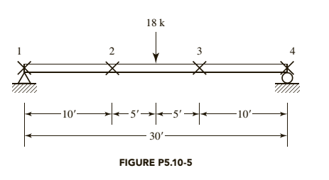
Chapter 5, Problem 5.10.5P
The given beam is laterally supported at the ends and at the
a. Use LRFD.
b. Use ASD.
Expert Solution & Answer

Trending nowThis is a popular solution!

Students have asked these similar questions
Determine the design moment capacity of the beam
with given properties below.
bf = 550mm
%3D
bw = 350mm
%3D
tf = 50mm
%D
d = 370mm
d' = 100mm
%D
fc' = 34.5 MPa
%3D
fy
= 400 MPa
As = 6 - 28mm bars
%D
a. USE NSCP 2001, Mu =
kN-m
b. USE NSCP 2015, Mu =
kN-m
A variable cross-sectional beam is pinned from the point B by BD bar as shown. Flexural rigidity of
AB and BC beams are 2El and EI, respectively. If the axial rigidity of the BD bar is EA, Determine
the reaction forces at the point A by using,
Mohr method
7
AL ).
3
EA
L
P
E2I
C EI
Use A 992 Steel and Select the most economical W shape for the beam shown
in the figure below. The beam weight is not included in the service
loads shown. Do not check deflection. Assume continuous Lateral support.
K
6
IPD = lok
PL=20k
*
161
1
WD= 3-33 K/F+
WL=6-67 k/Ft
-xhul
Chapter 5 Solutions
Steel Design (Activate Learning with these NEW titles from Engineering!)
Ch. 5 - Prob. 5.2.1PCh. 5 - Prob. 5.2.2PCh. 5 - Verify the value of Zx for a W1850 that is...Ch. 5 - Prob. 5.2.4PCh. 5 - Prob. 5.4.1PCh. 5 - Prob. 5.4.2PCh. 5 - Determine the smallest value of yield stress Fy,...Ch. 5 - Prob. 5.5.1PCh. 5 - Prob. 5.5.2PCh. 5 - Prob. 5.5.3P
Ch. 5 - Prob. 5.5.4PCh. 5 - Prob. 5.5.5PCh. 5 - Prob. 5.5.6PCh. 5 - Prob. 5.5.7PCh. 5 - Prob. 5.5.8PCh. 5 - Prob. 5.5.9PCh. 5 - If the beam in Problem 5.5-9 i5 braced at A, B,...Ch. 5 - Prob. 5.5.11PCh. 5 - Prob. 5.5.12PCh. 5 - Prob. 5.5.13PCh. 5 - Prob. 5.5.14PCh. 5 - Prob. 5.5.15PCh. 5 - Prob. 5.5.16PCh. 5 - Prob. 5.6.1PCh. 5 - Prob. 5.6.2PCh. 5 - Prob. 5.6.3PCh. 5 - Prob. 5.6.4PCh. 5 - Compute the nominal shear strength of an M107.5 of...Ch. 5 - Compute the nominal shear strength of an M1211.8...Ch. 5 - Prob. 5.8.3PCh. 5 - Prob. 5.8.4PCh. 5 - Prob. 5.10.1PCh. 5 - Prob. 5.10.2PCh. 5 - Same as Problem 5.10-2, except that lateral...Ch. 5 - Prob. 5.10.4PCh. 5 - The given beam is laterally supported at the ends...Ch. 5 - Prob. 5.10.6PCh. 5 - Prob. 5.10.7PCh. 5 - Prob. 5.11.1PCh. 5 - Prob. 5.11.2PCh. 5 - Prob. 5.11.3PCh. 5 - Prob. 5.11.4PCh. 5 - Prob. 5.11.5PCh. 5 - Prob. 5.11.6PCh. 5 - Prob. 5.11.7PCh. 5 - Prob. 5.11.8PCh. 5 - Prob. 5.11.9PCh. 5 - Prob. 5.12.1PCh. 5 - Prob. 5.12.2PCh. 5 - Prob. 5.12.3PCh. 5 - Prob. 5.13.1PCh. 5 - Prob. 5.13.2PCh. 5 - Prob. 5.14.1PCh. 5 - Prob. 5.14.2PCh. 5 - Prob. 5.14.3PCh. 5 - Prob. 5.14.4PCh. 5 - Prob. 5.15.1PCh. 5 - Prob. 5.15.2PCh. 5 - Prob. 5.15.3PCh. 5 - Prob. 5.15.4PCh. 5 - Prob. 5.15.5PCh. 5 - Prob. 5.15.6PCh. 5 - Prob. 5.15.7PCh. 5 - Same as Problem 5.15-7, except that the sag rods...
Knowledge Booster


Learn more about
Need a deep-dive on the concept behind this application? Look no further. Learn more about this topic, civil-engineering and related others by exploring similar questions and additional content below.Similar questions
- How much service live load, in kips per foot, can be supported? The member weight is the only dead load. The axial compressive load consists of a service dead load of 10 kips and a service live load of 20 kips. Do not consider moment amplification. Bending is about the x axis, and the steel is A992. a. Use LRFD. b. Use ASD.arrow_forwardThe AD beam, which is fixed at left end, is under various loads as shown below. a) Draw internal load diagrams (Nx, Vy, M2) using the method of section. b) Determine the state of stress at points G, H and I for section B. c) For the corresponding points, indicate the results (i.e. stress components) on a differential element. b2 A B G М F2 2l h bi GIVEN DATA: Fo = 10000 N, F1 1200 N, F2 = 1000 N, qo = 50 N/cm, Mo = 50000 Nem, l = 25 cm bi = 10 cm, b2 = 20 cm, h 12 cm, t 1 cmarrow_forwardQI/ A beam carries the loads shown in figure, if the tensile stress must not exceed 20 MPa and the compression stress 70MPa. Find the maximum value of load P Som, r W=2-5p W/m - P Lflj Ko ; - 3,‘, ) o Jo 1 er -1 /i e,arrow_forward
- For the given properties of beam below. Design the reinforcements of the beam. d'=75 mm b=400 mm d=580 mm fc'=35 MPa fy=320 MPa Mu=1000000000N mm Input is 0 in As' if compression bars are not needed. A. USE NSCP 2001, As = mm2, As' = mm2 B. USE NSCP 2015, As = mm2, As' = mm2 %3Darrow_forwardDetermine the design strength of the beam(properties given below) and the safe service live load if the service dead load is 320 kN.m.Use f'c =22 Mpa and fy=415 MPa. given properties: b=400 mm d'=70 mm d=620 mm As=10-28 mm A's=3-25 mm bars hello please answer this thanks ☺️arrow_forwardDETERMINE THE THE IS MAXIMUM SAFE SERVICE LIVE LOAD THAT THE BEAM CAN CAN CARRY IF SERVICE DEAD L O A D THE BEAM WEIGHT OF THE BEAM SECTION fy = 415 MPa. TOP BARS BOTTOM BARS ARE CENTER DISTANCE 12 KM/M INCLUDING AND BASED ON THE CAPACITY SHOWN. fc : 40 MPa AND ARE 6-32 mm. AND ARE - 3 - 28 mm. CENTER TO 3 BETWEEN THE USE 2015 NSCP Is 108 mm 00 0 0 300 G ט1 108 352 70. A (1 7.2m B TOP BAR LAYERS ↓ 6.7M C OMarrow_forward
- Question 27 1 points Save Ans A built up l-section is formed from plates welded together as shown in the figure. It is to be used as a column L = 3.8 m long. All elements are A36 steel and connected such the section is fully effective Using the following properties, calculate the flexural buckling stress, Fcr, in MPa using theoretical k. Flanges: b = 150 mm, te = 18 mm Web: h = 310 mm, tw = 7 mm Write your final answer in two decimal places only. I. tfarrow_forwardConsider the simply supported truss as defined in the figure and parameter table. Find the force in members CD, HD, and HG. Follow the convention the tension is positive and compression is negative. A 1910 P. B cc 000 BY NỌ SA 2021 Cathy Zupke L₂ parameter value L₁ 1.5 L2 1.5 L3 2.5 LA 2 1.5 1.5 30 50 60 60 L5 L6 P₁ P₂ P3 P₁ units H # G P₁ E F The force in member CD = The force in member HD = The force in member HG = m m EEEEEZZ m m m L3 KN KN ↑ KN KN KN 3arrow_forwardQ1: A circular steel rod ABCD is loaded as shown below. Use the following data to Find the maximum stress and the deformation (AL) of the rod. Take E = 200 L3=1350 GPa. L2=2150 A L1 E Dia. 1 L1=1350 Р3-25 P1 L2 Dia. 2 P2=40 P2 P1=105 Dia2=45 L3 P3 D D 35 mm o Dia1=60arrow_forward
- 2. Given a simply supported beam shown in figure below with the cross section at maximum moment. The beam supports a uniform service dead load of WDL =30 kN/m (excluding own weight of beam), PLL = 270 kN. Use fc' = 30 MPa; fy = 400 MPa. Calculate design strength M, for the cross section shown in the figure. Check the strains in the steel ɛsi. P, LL 75 100 - - 75 90 W. DL 710 650 5Ф30 15000 mm-arrow_forwardCheck the slenderness of the steel section against Local Buckling. 340 mm Use Fy = 800 MPa. O Compact Slender I O Adequate 400 mm None of the choices 30 mm 20 mm 20 mmarrow_forwardQ1: A circular steel rod ABCD is loaded as shown below. Use the following data to Find the maximum stress and the deformation (AL) of the rod. Take E= 200 GPa. A P1 L1 E Dia. 1 L2 Dia. 2 C L3 P2 30 mm o P3 Dia. 1 Dia. 2 P1 P2 P3 L1 L2 L3 Name (mm) (mm) (kN) (kN) (kN) (mm) (mm) (mm) 45 40 100 35 30 1300 2100 1300arrow_forward
arrow_back_ios
SEE MORE QUESTIONS
arrow_forward_ios
Recommended textbooks for you
 Steel Design (Activate Learning with these NEW ti...Civil EngineeringISBN:9781337094740Author:Segui, William T.Publisher:Cengage Learning
Steel Design (Activate Learning with these NEW ti...
Civil Engineering
ISBN:9781337094740
Author:Segui, William T.
Publisher:Cengage Learning
The History of Iron and Steel; Author: Real Engineering;https://www.youtube.com/watch?v=7E__zqy6xcw;License: Standard Youtube License