
Mechanics of Materials, 7th Edition
7th Edition
ISBN: 9780073398235
Author: Ferdinand P. Beer, E. Russell Johnston Jr., John T. DeWolf, David F. Mazurek
Publisher: McGraw-Hill Education
expand_more
expand_more
format_list_bulleted
Concept explainers
Videos
Textbook Question
Chapter 6, Problem 94RP
Knowing that a given vertical shear V causes a maximum shearing stress of 75 MPa in the hat-shaped extrusion shown, determine the corresponding shearing stress at (a) point a, (b) point b.
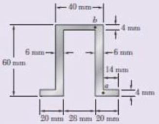
Fig. p6.94
Expert Solution & Answer
Want to see the full answer?
Check out a sample textbook solution
Students have asked these similar questions
Knowing that a given vertical shear V causes a maximum shearing stress of 50 MPa in a thin-walled member having the cross section shown, determine the corresponding shearing stress at (a) point a, (b) point b, (c) point c.
A square box beam is made of two 20 x 80-mm planks and two 20 x 120-mm planks nailed together as shown. Knowing that the spacing between the nails is s= 30 mm and that the vertical shear in the beam is V=1200 N, determine (a) the shearing force in each nail, (b) the maximum shearing stress in the beam.
Three boards, each of 1.5 x3.5-in. rectangular cross section, are nailed together to form a beam that is subjected to a vertical shear of 250 lb. Knowing that the spacing between each pair of nails is 2.5 in., determine the shearing force in each nail.
Chapter 6 Solutions
Mechanics of Materials, 7th Edition
Ch. 6.2 - Three full-size 50 100-mm boards are nailed...Ch. 6.2 - For the built-up beam of Prob. 6.1, determine the...Ch. 6.2 - Three boards, each 2 in. thick, are nailed...Ch. 6.2 - A square box beam is made of two 20 80-mm planks...Ch. 6.2 - The American Standard rolled-steel beam shown has...Ch. 6.2 - The beam shown is fabricated by connecting two...Ch. 6.2 - A column is fabricated by connecting the...Ch. 6.2 - The composite beam shown is fabricated by...Ch. 6.2 - 6.9 through 6.12 For beam and loading shown,...Ch. 6.2 - 6.9 through 6.12 For beam and loading shown,...
Ch. 6.2 - 6.9 through 6.12 For beam and loading shown,...Ch. 6.2 - 6.9 through 6.12 For beam and loading shown,...Ch. 6.2 - 6.13 and 6.14 For a beam having the cross section...Ch. 6.2 - 6.13 and 6.14 For a beam having the cross section...Ch. 6.2 - For a timber beam having the cross section shown,...Ch. 6.2 - Two steel plates of 12 220-mm rectangular cross...Ch. 6.2 - Two W8 31 rolled sections may be welded at A and...Ch. 6.2 - For the beam and. loading shown, determine the...Ch. 6.2 - Fig. P6.19 6.19 A timber beam AB of length L and...Ch. 6.2 - A timber beam AB of Length L and rectangular cross...Ch. 6.2 - 6.21 and 6.22 For the beam and loading shown,...Ch. 6.2 - 6.21 and 6.22 For the beam and loading shown,...Ch. 6.2 - 6.23 and 6.24 For the beam and loading shown,...Ch. 6.2 - 6.23 and 6.24 For the beam and loading shown,...Ch. 6.2 - 6.25 through 6.28 A beam having the cross section...Ch. 6.2 - 6.25 through 6.28 A beam having the cross section...Ch. 6.2 - Prob. 27PCh. 6.2 - 6.25 through 6.28 A beam having the cross section...Ch. 6.5 - The built-up timber beam shown is subjected to a...Ch. 6.5 - The built-up beam shown is made by gluing together...Ch. 6.5 - The built-up beam was made by gluing together...Ch. 6.5 - Several wooden planks are glued together to form...Ch. 6.5 - The built-up wooden beam shown is subjected to a...Ch. 6.5 - Knowing that a W360 122 rolled-steel beam is...Ch. 6.5 - 6.35 and 6.36 An extruded aluminum beam has the...Ch. 6.5 - 6.35 and 6.36 An extruded aluminum beam has the...Ch. 6.5 - Knowing that a given vertical shear V causes a...Ch. 6.5 - The vertical shear is 1200 lb in a beam having the...Ch. 6.5 - The vertical shear is 1200 lb in a beam having the...Ch. 6.5 - 6.40 and 6.47 The extruded aluminum beam has a...Ch. 6.5 - Prob. 41PCh. 6.5 - Prob. 42PCh. 6.5 - Three planks are connected as shown by bolts of...Ch. 6.5 - A beam consists of three planks connected as shown...Ch. 6.5 - A beam consists of five planks of 1.5 6-in. cross...Ch. 6.5 - Four L102 102 9.5 steel angle shapes and a 12 ...Ch. 6.5 - A plate of 14-in. thickness is corrugated as shown...Ch. 6.5 - Prob. 48PCh. 6.5 - An extruded beam has the cross section shown and a...Ch. 6.5 - Prob. 50PCh. 6.5 - The design of a beam calls for connecting two...Ch. 6.5 - The cross section of an extruded beam is a hollow...Ch. 6.5 - Prob. 53PCh. 6.5 - Prob. 54PCh. 6.5 - Prob. 55PCh. 6.5 - 6.56 and 6.57 A composite beam is made by...Ch. 6.5 - 6.56 and 6.57 A composite beam is made by...Ch. 6.5 - Prob. 58PCh. 6.5 - Prob. 59PCh. 6.5 - Prob. 60PCh. 6.6 - 6.61 through 6.64 Determine the location of the...Ch. 6.6 - 6.61 through 6.64 Determine the location of the...Ch. 6.6 - 6.61 through 6.64 Determine the location of the...Ch. 6.6 - Prob. 64PCh. 6.6 - 6.65 through 6.68 An extruded beam has the cross...Ch. 6.6 - 6.65 through 6.68 An extruded beam has the cross...Ch. 6.6 - 6.65 through 6.68 An extruded beam has the cross...Ch. 6.6 - 6.65 through 6.68 An extruded beam has the cross...Ch. 6.6 - 6.69 through 6.74 Determine the location of the...Ch. 6.6 - Prob. 70PCh. 6.6 - Prob. 71PCh. 6.6 - Prob. 72PCh. 6.6 - Prob. 73PCh. 6.6 - Prob. 74PCh. 6.6 - Prob. 75PCh. 6.6 - 6.75 and 6.76 A thin-walled beam has the cross...Ch. 6.6 - 6.77 and 6.78 A thin-walled beam of uniform...Ch. 6.6 - Prob. 78PCh. 6.6 - Prob. 79PCh. 6.6 - Prob. 80PCh. 6.6 - Prob. 81PCh. 6.6 - Prob. 82PCh. 6.6 - Prob. 83PCh. 6.6 - Prob. 84PCh. 6.6 - Prob. 85PCh. 6.6 - Solve Prob. 6.85, assuming that the thickness of...Ch. 6.6 - Prob. 87PCh. 6.6 - Prob. 88PCh. 6 - Three boards are nailed together to form the beam...Ch. 6 - For the beam and loading shown, consider section...Ch. 6 - For the wide-flange beam with the loading shown,...Ch. 6 - For the beam and loading shown, consider section...Ch. 6 - The built-up timber beam is subjected to a 1500-lb...Ch. 6 - Knowing that a given vertical shear V causes a...Ch. 6 - Three planks are connected as shown by bolts of...Ch. 6 - Three 1 18-in. steel plates are bolted to four L6...Ch. 6 - The composite beam shown is made by welding C200 ...Ch. 6 - Prob. 98RPCh. 6 - A thin-walled beam of uniform thickness has the...Ch. 6 - Determine the location of the shear center O of a...
Knowledge Booster


Learn more about
Need a deep-dive on the concept behind this application? Look no further. Learn more about this topic, mechanical-engineering and related others by exploring similar questions and additional content below.Similar questions
- Four L102 x 102 x 9.5 steel angle shapes and a 12 x 400-mm steel plate are bolted together to form a beam with the cross section shown. The bolts are of 22-mm diameter and are spaced longitudinally every 120 mm. Knowing that the beam is subjected to a vertical shear of 240 kN, determine the average shearing stress in each bolt.arrow_forwardA beam consists of three planks connected by steel bolts with a lon-gitudinal spacing of 225 mm. Knowing that the shear in the beam is vertical and equal to 6 kN and that the allowable average shearing stress in each bolt is 60 MPa, determine the smallest permissible bolt diameter that can be usedarrow_forwardThe design specifications of a 1.2-m-long solid transmission shaft require that the angle of twist of the shaft not exceed 4° when a torque of 750 N·m is applied. Determine the required diameter of the shaft, knowing that the shaft is made of a steel with an allowable shearing stress of 90 MPa and a modulus of rigidity of 77.2 GPa.arrow_forward
- The wooden members A and B are to be joined by plywood splice plates that will be fully glued on the surfaces in contact. As part of the design of the joint, and knowing that the clearance between the ends of the members is to be 8 mm, determine the smallest allowable length L if the average shearing stress in the glue is not to exceed 800 kPa.arrow_forwardLink AB, of width b = 50 mm and thickness t = 6 mm, is used to support the end of a horizontal beam. Knowing that the average normal stress in the link is –140 MPa, and that the average shearing stress in each of the two pins is 80 MPa, determine (a) the diameter d of the pins, (b) the average bearing stress in the link.arrow_forwardThree 1 x 18-in. steel plates are bolted to four L6 x 6 x 1 angles to form a beam with the cross section shown. The bolts have a 78-in. diameter and are spaced longitudinally every 5 in. Knowing that the allowable average shearing stress in the bolts is 12 ksi, determine the largest permissible vertical shear in the beam. (Given: Ix= 6123 in4.)arrow_forward
- Shaft BC is hollow with inner and outer diameters of 90 mm and 120 mm, respectively. Shafts AB and CD are solid and of diameter d. For the loading shown, determine (a) the maximum and minimum shearing stress in shaft BC, (b) the required diameter d of shafts AB and CD if the allowable shear-ing stress in these shafts is 65 MPa.arrow_forwardFor the state of plane stress shown, determine the largest value of σy for which the maximum in-plane shearing stress is equal to or less than 75 MPaarrow_forwardKnowing that an 8-mm-diameter hole has been drilled through each of the shafts AB, BC, and CD, determine(a) the shaft in which the maximum shearing stress occurs,(b) the magnitude of that stressarrow_forward
- The solid shaft shown is formed of a brass for which the allowable shearing stress is 55 MPa. Neglecting the effect of stress concentrations, determine the smallest diameters dAB and dBC for which the allowable shearing stress is not exceeded. Take TC = 300 N·m.arrow_forwardTwo solid steel shafts are fitted with flanges that are then connected by bolts as shown. The bolts are slightly undersized and permit a 1.5° rotation of one flange with respect to the other before the flanges begin to rotate as a single unit. Knowing that G = 77.2 GPa, determine the maximum shearing stress in each shaft when a torque T of magnitude 500 N·m is applied to the flange indicated.The torque T is applied to flange Carrow_forwardA torque of magnitude T=12 kN·m is applied to the end of a tank containing compressed air under a pressure of 8 MPa. Knowing that the tank has a 180-mm inner diameter and a 12-mm wall thickness, determine the maximum normal stress and the maximum in-plane shearing stress in the tank.arrow_forward
arrow_back_ios
SEE MORE QUESTIONS
arrow_forward_ios
Recommended textbooks for you
 Elements Of ElectromagneticsMechanical EngineeringISBN:9780190698614Author:Sadiku, Matthew N. O.Publisher:Oxford University Press
 Mechanics of Materials (10th Edition)Mechanical EngineeringISBN:9780134319650Author:Russell C. HibbelerPublisher:PEARSON
 Thermodynamics: An Engineering ApproachMechanical EngineeringISBN:9781259822674Author:Yunus A. Cengel Dr., Michael A. BolesPublisher:McGraw-Hill Education
 Control Systems EngineeringMechanical EngineeringISBN:9781118170519Author:Norman S. NisePublisher:WILEY
 Mechanics of Materials (MindTap Course List)Mechanical EngineeringISBN:9781337093347Author:Barry J. Goodno, James M. GerePublisher:Cengage Learning
 Engineering Mechanics: StaticsMechanical EngineeringISBN:9781118807330Author:James L. Meriam, L. G. Kraige, J. N. BoltonPublisher:WILEY
Elements Of Electromagnetics
Mechanical Engineering
ISBN:9780190698614
Author:Sadiku, Matthew N. O.
Publisher:Oxford University Press
Mechanics of Materials (10th Edition)
Mechanical Engineering
ISBN:9780134319650
Author:Russell C. Hibbeler
Publisher:PEARSON
Thermodynamics: An Engineering Approach
Mechanical Engineering
ISBN:9781259822674
Author:Yunus A. Cengel Dr., Michael A. Boles
Publisher:McGraw-Hill Education
Control Systems Engineering
Mechanical Engineering
ISBN:9781118170519
Author:Norman S. Nise
Publisher:WILEY
Mechanics of Materials (MindTap Course List)
Mechanical Engineering
ISBN:9781337093347
Author:Barry J. Goodno, James M. Gere
Publisher:Cengage Learning
Engineering Mechanics: Statics
Mechanical Engineering
ISBN:9781118807330
Author:James L. Meriam, L. G. Kraige, J. N. Bolton
Publisher:WILEY
Understanding Stress Transformation and Mohr's Circle; Author: The Efficient Engineer;https://www.youtube.com/watch?v=_DH3546mSCM;License: Standard youtube license