
SYSTEM DYNAMICS>LOOSELEAF<
3rd Edition
ISBN: 9781260163087
Author: Palm
Publisher: MCG
expand_more
expand_more
format_list_bulleted
Concept explainers
Videos
Textbook Question
Chapter 7, Problem 7.23P
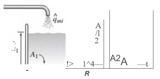
(a) Develop a model of the two liquid heights in the system shown in Figure P7.23. The inflow rate q,ni(t) is a mass flow rate,
(b) Using the values = R, R2= 3R. A | = A, and A2— 4A, find the transfer function
Expert Solution & Answer
Want to see the full answer?
Check out a sample textbook solution
Students have asked these similar questions
A one-fifth scale model of a water turbine is tested in a laboratory at T = 20°C. The diameter of the model is 8.0 cm, its volume flow rate is 17.0 m3 /h, it spins at 1500 rpm, and it operates with a net head of 15.0 m. At its best efficiency point, it delivers 450 W of shaft power. Calculate the efficiency of the model turbine. What is the most likely kind of turbine being tested?
(a) If the boundary layer velocity profile for y ≤ δ is given by where U is the velocity at a distance y from the surface, δ is the boundary layer thickness and Ue is the freestream velocity. (i) Find the ratio of the displacement thickness to the boundary layer thickness (this is a number). (ii) Find the ratio of the momentum thickness to the boundary layer thickness (this is a number). (b) Air enters a two-dimensional duct with a uniform velocity profile. As the boundary layers on the top and bottom walls grow with downstream distance, the velocity in the freestream tends to increase. However, if the walls diverged with downstream distance so that the freestream velocity remained constant, express the angle of divergence of the walls in terms of the boundary layer displacement thickness δ∗ and the distance along the duct x. (c) A laminar boundary layer is observed to grow on a flat plate of width w and length x = L such that the pressure is…
The transfer function of the following system is, G(s)
Chapter 7 Solutions
SYSTEM DYNAMICS>LOOSELEAF<
Ch. 7 - Prob. 7.1PCh. 7 - Refer to the water storage and supply system shown...Ch. 7 - Prob. 7.3PCh. 7 - In Figure P7.4 the piston of area A is connected...Ch. 7 - Refer to Figure 7.1.4a. and suppose that p\ — p2=...Ch. 7 - Pure water flows into a mixing tank of volume V =...Ch. 7 - Consider the mixing tank treated in Problem 7.6....Ch. 7 - Derive the expression for the fluid capacitance of...Ch. 7 - Prob. 7.9PCh. 7 - Prob. 7.10P
Ch. 7 - 7.11 Derive the expression for the capacitance of...Ch. 7 - Air flows in a certain cylindrical pipe 1 m long...Ch. 7 - Derive the expression for the linearized...Ch. 7 - Consider the cylindrical container treated in...Ch. 7 - A certain tank has a bottom area A = 20 m2. The...Ch. 7 - A certain tank has a circular bottom area A = 20...Ch. 7 - The water inflow rate to a certain tank was kept...Ch. 7 - Prob. 7.18PCh. 7 - Prob. 7.19PCh. 7 - In the liquid level system shown in Figure P7.20,...Ch. 7 - The water height in a certain tank was measured at...Ch. 7 - Derive the model for the system shown in Figure...Ch. 7 - (a) Develop a model of the two liquid heights in...Ch. 7 - Prob. 7.24PCh. 7 - Design a piston-type damper using an oil with a...Ch. 7 - Prob. 7.26PCh. 7 - 7.27 An electric motor is sometimes used to move...Ch. 7 - Prob. 7.28PCh. 7 - Prob. 7.29PCh. 7 - Figure P7.3O shows an example of a hydraulic...Ch. 7 - Prob. 7.31PCh. 7 - Prob. 7.32PCh. 7 - Prob. 7.33PCh. 7 - Prob. 7.34PCh. 7 - Prob. 7.35PCh. 7 - Prob. 7.36PCh. 7 - Prob. 7.37PCh. 7 - (a) Determine the capacitance of a spherical tank...Ch. 7 - Obtain the dynamic model of the liquid height It...Ch. 7 - Prob. 7.40PCh. 7 - Prob. 7.41PCh. 7 - Prob. 7.42PCh. 7 - Prob. 7.43PCh. 7 - Prob. 7.44PCh. 7 - Prob. 7.45PCh. 7 - The copper shaft shown in Figure P7.46 consists of...Ch. 7 - A certain radiator wall is made of copper with a...Ch. 7 - A particular house wall consists of three layers...Ch. 7 - A certain wall section is composed of a 12 in. by...Ch. 7 - Prob. 7.50PCh. 7 - Prob. 7.51PCh. 7 - A steel tank filled with water has a volume of...Ch. 7 - Prob. 7.53PCh. 7 - Prob. 7.54PCh. 7 - Prob. 7.55P
Knowledge Booster


Learn more about
Need a deep-dive on the concept behind this application? Look no further. Learn more about this topic, mechanical-engineering and related others by exploring similar questions and additional content below.Similar questions
- Explain the concept of transfer functions in system modeling and how they relate to Laplace transforms.arrow_forwardDescribe the concept of a transfer function in the context of system modeling. How is it used to represent a system's behavior?arrow_forward1) Obtain a state space model of the system. 2) Given m =1 kg, k = 1 N/m and b = 1 N.s/m is the system Controllable? 3) For what values of k,m,b the system is stable? Explain your answer?arrow_forward
- A large artery has an inner radius of 4×10⁻³ m, the flow rate of the blood is 1 cm3/s. Find (a) the mean and maximum velocities of the blood, (b) the pressure drop in an artery fragment 0.1 m long, (c) the power necessary to maintain this flow in said fragment, (d) the number of Reynolds. Consider that for blood: η = 2.08 × 10⁻³ Pas, ρ = 1.06 × 10³ kg / m3arrow_forwardQ2] A tank having cross sectional area of 0.2 m² is operating at steady state with an inlet flowrate of 1*10² m²/s, the flow-head characteristics are given by: 9. = 0.003 h + 0.0006 Where, q. = outlet flowrate, m?/s and h = tank level, m. a. Determine the transfer function relating inlet flowrate and liquid level with numerical values of the time constant and steady state gain. b. If the inlet flowrate increased from 1*10-3 m?/s to 1.1*10-3 m²/s for 200 s and then return to initial steady state value (pluse function). Find the level after 100 s and 300 s. Plot the response.arrow_forwardwater (ρ = 1000 kg / m ^ 3, v = 1.0 * 10 ^ -6 m ^ 2 / s, μ = 1.0 * 10 ^ -3 kg / ms) flows from a 50 cmm diameter pipe at 2 m / s . A model of this system will use air (ρ = 1.2 kg / m ^ 3, v = 1.5 * 10 ^ -5 m ^ 2 / s μ = 1.8 * 10 ^ -5 kg / ms) as fluid . Air velocity will be 30 m / s. Find the required pipe diameter to achieve dynamic similarity between model and prototype.arrow_forward
- Propose a centrifugal pump (brand and model) to transport 10 L/s of a fluid with a density of 1500 kg/m3 from a tank located on the first floor to a reactor on the second floor of the plant (8 meters in height). The reactor's operating pressure is 30 psig; the fluid is at 20 °C, and its viscosity is 15 cp. The pipeline on the pump discharge is 30 meters long (considering accessories are included). Neglect pressure losses in the pump suction. Propose the pipe diameter, schedule 40, commercial steel. Make any necessary assumptions. Select a pump capable of delivering a maximum flow of 15 L/s (remember that normal operation will be at 10 L/s) and discuss the price paid for this condition. Provide a copy of the pump curve indicating the operating point. Also, calculate the power consumption of the pump.arrow_forwardsystem modelling and analysısarrow_forwardTake the mass of the block is M(kilogram=Newton-second2/meter), the spring constant is K(Newton/meter), the coefficient of viscous friction is fv(Newton-second/meter), distance takenin time is x(t)(meter) and force used in the system is f(t)(Newton). Write the transfer functionsfor figure 1.1, and figure 1.2arrow_forward
- Describe the importance of system modeling in engineering and its applications.arrow_forwardSteady State flow exists in pipe that undergoes a gradual expansion from a diameter of 6in. Assuming constant density and the inlet flow velocity is 22.4 ft/sec. What is the size of the exit pipe if the exist flow velocity is 12.6 ft/sec?arrow_forwardA velocity of a vehicle is required to be controlled and maintained constant even if there are disturbances because of wind, or road surface variations. The forces that are applied on the vehicle are the engine force (u), damping/resistive force (b*v) that opposing the motion, and inertial force (m*a). A simplified model is shown in the free body diagram below. From the free body diagram, the ordinary differential equation of the vehicle is: m * dv(t)/ dt + bv(t) = u (t) Where: v (m/s) is the velocity of the vehicle, b [Ns/m] is the damping coefficient, m [kg] is the vehicle mass, u [N] is the engine force. Question: Assume that the vehicle initially starts from zero velocity and zero acceleration. Then, (Note that the velocity (v) is the output and the force (w) is the input to the system): 1. What is the order of this system?arrow_forward
arrow_back_ios
SEE MORE QUESTIONS
arrow_forward_ios
Recommended textbooks for you
 Elements Of ElectromagneticsMechanical EngineeringISBN:9780190698614Author:Sadiku, Matthew N. O.Publisher:Oxford University Press
 Mechanics of Materials (10th Edition)Mechanical EngineeringISBN:9780134319650Author:Russell C. HibbelerPublisher:PEARSON
 Thermodynamics: An Engineering ApproachMechanical EngineeringISBN:9781259822674Author:Yunus A. Cengel Dr., Michael A. BolesPublisher:McGraw-Hill Education
 Control Systems EngineeringMechanical EngineeringISBN:9781118170519Author:Norman S. NisePublisher:WILEY
 Mechanics of Materials (MindTap Course List)Mechanical EngineeringISBN:9781337093347Author:Barry J. Goodno, James M. GerePublisher:Cengage Learning
 Engineering Mechanics: StaticsMechanical EngineeringISBN:9781118807330Author:James L. Meriam, L. G. Kraige, J. N. BoltonPublisher:WILEY
Elements Of Electromagnetics
Mechanical Engineering
ISBN:9780190698614
Author:Sadiku, Matthew N. O.
Publisher:Oxford University Press
Mechanics of Materials (10th Edition)
Mechanical Engineering
ISBN:9780134319650
Author:Russell C. Hibbeler
Publisher:PEARSON
Thermodynamics: An Engineering Approach
Mechanical Engineering
ISBN:9781259822674
Author:Yunus A. Cengel Dr., Michael A. Boles
Publisher:McGraw-Hill Education
Control Systems Engineering
Mechanical Engineering
ISBN:9781118170519
Author:Norman S. Nise
Publisher:WILEY
Mechanics of Materials (MindTap Course List)
Mechanical Engineering
ISBN:9781337093347
Author:Barry J. Goodno, James M. Gere
Publisher:Cengage Learning
Engineering Mechanics: Statics
Mechanical Engineering
ISBN:9781118807330
Author:James L. Meriam, L. G. Kraige, J. N. Bolton
Publisher:WILEY
Fluid Mechanics - Viscosity and Shear Strain Rate in 9 Minutes!; Author: Less Boring Lectures;https://www.youtube.com/watch?v=_0aaRDAdPTY;License: Standard youtube license