
Foundations of Materials Science and Engineering
6th Edition
ISBN: 9781259696558
Author: SMITH
Publisher: MCG
expand_more
expand_more
format_list_bulleted
Concept explainers
Videos
Textbook Question
Chapter 7.10, Problem 60SEP
The components in Figure P7.60 are high-strength steel race car transmission shafts, which are cyclically loaded in torsion and with some bending. The one at the bottom of Figure P7.60a is fractured. Figure P7.60b shows a higher-magnification image of the fracture path around the shaft. Figure P7.60c shows the cross section of the fractured shaft. Based on this visual evidence, speculate as much as possible about what happened to this shaft and where the fracture began. Especially, list your observations of Figure P7.60c.
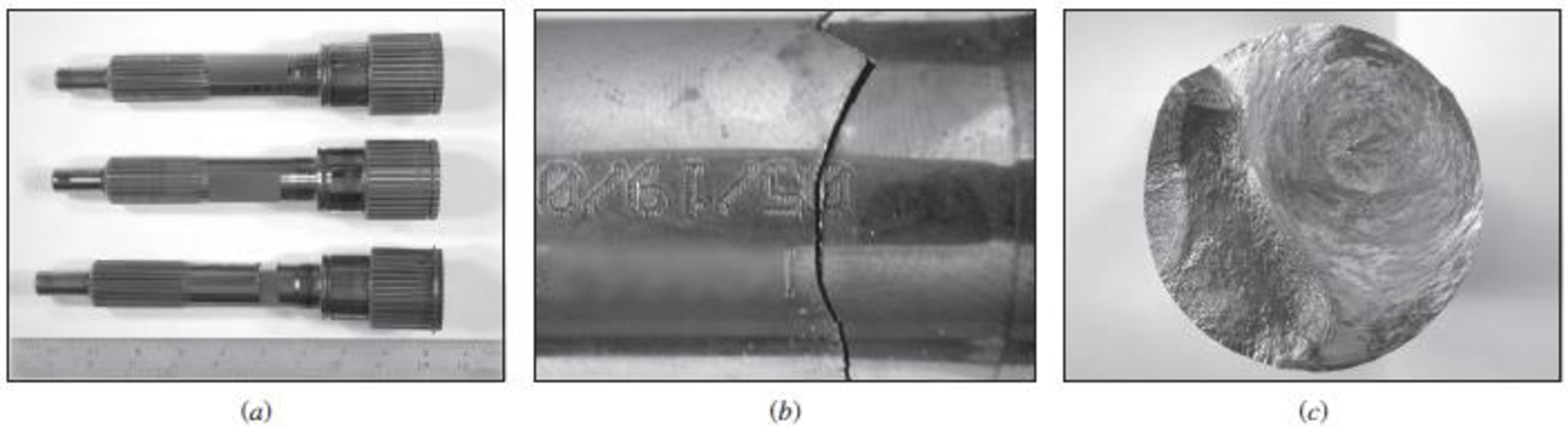
Figure P7.60
Expert Solution & Answer
Want to see the full answer?
Check out a sample textbook solution
Students have asked these similar questions
A three-point bending test is performed on a silicon carbide block that is 10 cm long, 1.5 cm wide, and 0.6 cm thick, and that is supported by two separate supports.7.5 cm. The sample breaks when a bending of 0.09 mm is recorded. The flexural modulus of silicon carbide is 480 GPa. Assume that no plastic deformation has occurred. Calculate:
(a) The force that caused the fracture and(b) Flexural strength.
(a) A core sample having length to diameter ratio of 2.5
experienced a strain of 0.94 after being stretched. If the core had an
initial length of 8 cm and was able to withstand a load of 500 N
before breaking, calculate:
The resulting length before failure
The tensile strength
(b) If the core sample above is subjected to a uniaxial compression
test resulting in load, axial deformation and circumferential
deformation of 350 N, 1.5 and 0.47 respectively at failure,
calculate:
The uniaxial compressive strength, σc
The Young’s modulus, E
The Poisson’s ratio,μ
You are called as an expert witness to analyze the fracture of a sintered silicon carbide plate that was fractured in bending when a blunt load was applied to the plate center. Measurement of the distance between the fracture origin and the mirror/mist boundary on the fracture surface gives a radius of 0.796 mm. You are given three pieces of the same SiC to test, and you determine that the mirror radius is 0.603, 0.203, and 0.162 mm for bending failure stress levels of 225, 368, and 442 MPa, respectively. What is your estimate of the stress present at the time of fracture for the original plate?
Chapter 7 Solutions
Foundations of Materials Science and Engineering
Ch. 7.10 - What are the characteristics of the surface of a...Ch. 7.10 - Prob. 2KCPCh. 7.10 - Prob. 3KCPCh. 7.10 - Prob. 4KCPCh. 7.10 - Prob. 5KCPCh. 7.10 - Prob. 6KCPCh. 7.10 - Prob. 7KCPCh. 7.10 - Prob. 8KCPCh. 7.10 - Prob. 9KCPCh. 7.10 - How does the carbon content of a plain-carbon...
Ch. 7.10 - Describe a metal fatigue failure.Ch. 7.10 - What two distinct types of surface areas are...Ch. 7.10 - Prob. 13KCPCh. 7.10 - Prob. 14KCPCh. 7.10 - Prob. 15KCPCh. 7.10 - Describe the four basic structural changes that...Ch. 7.10 - Describe the four major factors that affect the...Ch. 7.10 - Prob. 18KCPCh. 7.10 - Prob. 19KCPCh. 7.10 - Prob. 20KCPCh. 7.10 - Prob. 21KCPCh. 7.10 - Determine the critical crack length for a through...Ch. 7.10 - Determine the critical crack length for a through...Ch. 7.10 - The critical stress intensity (KIC) for a material...Ch. 7.10 - What is the largest size (in mm) of internal...Ch. 7.10 - A Ti-6Al-4V alloy plate contains an internal...Ch. 7.10 - Using the equation KIC=fa, plot the fracture...Ch. 7.10 - (a) Determine the critical crack length (mm) for a...Ch. 7.10 - A fatigue test is made with a maximum stress of 25...Ch. 7.10 - A fatigue test is made with a mean stress of...Ch. 7.10 - A large, flat plate is subjected to...Ch. 7.10 - Prob. 32AAPCh. 7.10 - Refer to Problem 7.31: Compute the final critical...Ch. 7.10 - Prob. 34AAPCh. 7.10 - Prob. 35AAPCh. 7.10 - Equiaxed MAR-M 247 alloy (Fig. 7.31) is used to...Ch. 7.10 - Prob. 37AAPCh. 7.10 - If DS CM 247 LC alloy (middle graph of Fig. 7.31)...Ch. 7.10 - Prob. 39AAPCh. 7.10 - Prob. 40AAPCh. 7.10 - Prob. 41SEPCh. 7.10 - Prob. 42SEPCh. 7.10 - A Charpy V-notch specimen is tested by the...Ch. 7.10 - Prob. 44SEPCh. 7.10 - Prob. 45SEPCh. 7.10 - Prob. 46SEPCh. 7.10 - Prob. 47SEPCh. 7.10 - Prob. 48SEPCh. 7.10 - Prob. 49SEPCh. 7.10 - Prob. 50SEPCh. 7.10 - While driving your car, a small pebble hits your...Ch. 7.10 - Prob. 52SEPCh. 7.10 - Prob. 53SEPCh. 7.10 - Prob. 54SEPCh. 7.10 - Prob. 56SEPCh. 7.10 - Prob. 57SEPCh. 7.10 - Prob. 58SEPCh. 7.10 - Prob. 59SEPCh. 7.10 - The components in Figure P7.60 are high-strength...
Knowledge Booster


Learn more about
Need a deep-dive on the concept behind this application? Look no further. Learn more about this topic, mechanical-engineering and related others by exploring similar questions and additional content below.Similar questions
- Calculate the axial deformation of a 1” round steel bar, 1 foot long of material, C1045, when it is subjected to a force of 60,000 axially. Modulus of elasticity = 30 x 10^6 psi. Note: All units are in SI, for your reference.arrow_forwardA specimen of a 4340 steel alloy having a plane strain fracture toughness of 25 MPa√m is exposed to a stress of 500 MPa. -Will this specimen experience fracture if it is known that the largest surface crack is 0.5 mm? Please explain why. Assume the parameter Y has a value of 1.0.arrow_forwardFor a large plate, the geometry factor, f, is 1.03. Suppose a steel casting alloy has a critical fracture toughness of 78,886 psi*in1/2. The steel will be exposed to a stress of 40,295 psi during service. Calculate the minimum size of an edge crack that will grow. Repeat the calculation for Al2O3 with a fracture toughness of 1,600 psi*in1/2. How many times larger is the minimum size edge crack in the steel versus the alumina?arrow_forward
- A metallic rod with an initial diameter of 10 mm and an initial length of 50 mm is subjected to the tensile test. After the fracture, the final length was measured as 51.8 mm, and the final diameter was measured as 9.5 mm.(a) Calculate modulus of elasticity, ultimate tensile strength, elongation at fracture in %,reduction of area in %, true stress at maximum load, true strain at maximum load, strain hardening exponent, strength coefficient.?arrow_forward8.a) Calculate the theoretical fracture strength of a brittle material wherein fracture occurs by propagation of an elliptically shaped 0.25 mm surface crack with a 1.2 × 10⁻³ mm tip radius under an applied 1200 MPa stress. b) If the specific surface energy for a material is 0.30 J/m2 and its elastic modulus is 69 GPa, calculate the minimum stress required for propagation of a surface crack 0.05 mm in length. Based on this calculation, estimate the materials fracture toughness.arrow_forwardA cylindrical specimen of brass material 11mm in diameter and 110mm long is elastically deformed in tension with a force of 7853N which produces a 4.25x10^-3mm reduction in specimen diameter. Calculate the Poissons ratio for this materialarrow_forward
- Imagine that you have two cracked components that are identical to one another except that Component A has a preexisting crack that is twice as long as that found in Component B. Does that mean that the fatigue lifetime of Component A will be 50% that of Component B?arrow_forwardA crack has been discovered along the edge of a reinforcing rib in titanium housing. The rib is 0.5 inches thick and 4.0 inches wide. The crack extends completely through the thickness and is about 1.20 inches long. If the housing is subjected to static loading only, and the maximumestimated loading produces a tensile load along the rib axis of 50,000 Ib, should the housing be removed from service? The housing material exhibits a yield strength of 150 ksi and a plane strain fracture toughness of 50 ksi in1/2.arrow_forwardA sample of giant reed is shaped into a beam with a square cross section of 15.5 mm by 15.5 mm. Two supports placed 22.1 mm apart support thesample and a load is applied halfway between the support points in order to test the force required to fracture the sample. If ultimate tensile strength is912 MPa, what would be the force F (newtons) required to cause failure?arrow_forward
- Draw a graph showing the elasticity, flexibility, and brittleness property in terms of stress and strain.arrow_forward(Suppose you need to design a tension test machine capable of testing specimens that have nominal ultimate stresses as high as σu = 100 ksi . How much force must the machine be capable of generating? Assume the testing specimen has the ASTM shape shown. Answer for this is 19.6 kip) (If the maximum nominal strain is ϵf = 0.7 just before the test specimen fractures and the test machine operates by moving only one grip, how far must that grip be designed to travel? The total length of the deforming part of the specimen is 3 in. Answer for this is 2.10 in) Do not know if this info is needed but this was the other 2 partsarrow_forwardIn the Table below Data for Mar M 247-a Nickel base superalloy is shown. (1) Plot the steady state strain rate and time to rupture to predict a relationship between the two variables. Provide an equation for the relationship that you see. (2) Give an explanation as to why the fracture elongation is going up with stress.arrow_forward
arrow_back_ios
SEE MORE QUESTIONS
arrow_forward_ios
Recommended textbooks for you
 Elements Of ElectromagneticsMechanical EngineeringISBN:9780190698614Author:Sadiku, Matthew N. O.Publisher:Oxford University Press
 Mechanics of Materials (10th Edition)Mechanical EngineeringISBN:9780134319650Author:Russell C. HibbelerPublisher:PEARSON
 Thermodynamics: An Engineering ApproachMechanical EngineeringISBN:9781259822674Author:Yunus A. Cengel Dr., Michael A. BolesPublisher:McGraw-Hill Education
 Control Systems EngineeringMechanical EngineeringISBN:9781118170519Author:Norman S. NisePublisher:WILEY
 Mechanics of Materials (MindTap Course List)Mechanical EngineeringISBN:9781337093347Author:Barry J. Goodno, James M. GerePublisher:Cengage Learning
 Engineering Mechanics: StaticsMechanical EngineeringISBN:9781118807330Author:James L. Meriam, L. G. Kraige, J. N. BoltonPublisher:WILEY
Elements Of Electromagnetics
Mechanical Engineering
ISBN:9780190698614
Author:Sadiku, Matthew N. O.
Publisher:Oxford University Press
Mechanics of Materials (10th Edition)
Mechanical Engineering
ISBN:9780134319650
Author:Russell C. Hibbeler
Publisher:PEARSON
Thermodynamics: An Engineering Approach
Mechanical Engineering
ISBN:9781259822674
Author:Yunus A. Cengel Dr., Michael A. Boles
Publisher:McGraw-Hill Education
Control Systems Engineering
Mechanical Engineering
ISBN:9781118170519
Author:Norman S. Nise
Publisher:WILEY
Mechanics of Materials (MindTap Course List)
Mechanical Engineering
ISBN:9781337093347
Author:Barry J. Goodno, James M. Gere
Publisher:Cengage Learning
Engineering Mechanics: Statics
Mechanical Engineering
ISBN:9781118807330
Author:James L. Meriam, L. G. Kraige, J. N. Bolton
Publisher:WILEY
Material Properties 101; Author: Real Engineering;https://www.youtube.com/watch?v=BHZALtqAjeM;License: Standard YouTube License, CC-BY