
Shigley's Mechanical Engineering Design (McGraw-Hill Series in Mechanical Engineering)
10th Edition
ISBN: 9780073398204
Author: Richard G Budynas, Keith J Nisbett
Publisher: McGraw-Hill Education
expand_more
expand_more
format_list_bulleted
Videos
Textbook Question
Chapter 8, Problem 75P
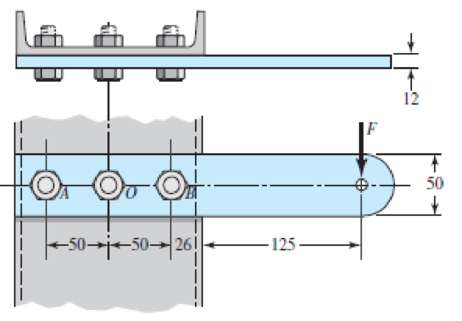
A vertical channel 152 × 76 (see Table A–7) has a cantilever beam bolted to it as shown. The channel is hot-rolled AISI 1006 steel. The bar is of hot-rolled AISI 1015 steel. The shoulder bolts are M10 × 1.5 ISO 5.8. Assume the bolt threads do not extend into the joint. For a design factor of 2.0, find the safe force F that can be applied to the cantilever.
Problem 8–75
Dimensions in millimeters.
Expert Solution & Answer
Want to see the full answer?
Check out a sample textbook solution
Students have asked these similar questions
The figure gives the cross-section of a grade 25 cast-iron pressure vessel. A total of N bolts are to be used to resist a separating force of 150 kN.
(a) Determine kb, km, and C.
(b) Find the number of bolts required for a load factor of 2 where the bolts may be reused when the joint is taken apart.
(c) With the number of bolts obtained in part (b), determine the realized load factor for overload, the yielding factor of safety, and the load factor for joint separation.
Use (SI) units as it applies
Link 2, shown in the figure, is 25 mm wide and 11 mm thick. It is made from low-carbon steel with Sy= 165 MPa. The pin joints are constructed with sufficient size and fit to provide good resistance to out-of-plane bending. Use Table 4-2 shown below for recommended values for C. Determine the following for link 2:
a.)Axial Force
b.)Yield factor of safety
c.) In-plane buckling factor of safety and Out-plane buckling factor of safety
A rigid coupling with 30 inches of bolt circle diameter transmits a torque of 18,000 lb-in. The coupling material has a yield strength of 90,000 psi. The coupling is fastened by six bolts. Assume design factor of N=3
Calculate the diameter of each bolt.
Chapter 8 Solutions
Shigley's Mechanical Engineering Design (McGraw-Hill Series in Mechanical Engineering)
Ch. 8 - A power screw is 25 mm in diameter and has a...Ch. 8 - Using the information in the footnote of Table...Ch. 8 - Show that for zero collar friction the efficiency...Ch. 8 - A single-threaded power screw is 25 mm in diameter...Ch. 8 - The machine shown in the figure can be used for a...Ch. 8 - The press shown for Prob. 8-5 has a rated load of...Ch. 8 - For the screw clamp shown, a force is applied at...Ch. 8 - The C clamp shown in the figure for Prob. 8-7 uses...Ch. 8 - Find the power required to drive a 1.5-in power...Ch. 8 - A single square-thread power screw has an input...
Ch. 8 - Prob. 11PCh. 8 - An M14 2 hex-head bolt with a nut is used to...Ch. 8 - Prob. 13PCh. 8 - A 2-in steel plate and a 1-in cast-iron plate are...Ch. 8 - Repeat Prob. 8-14 with the addition of one 12 N...Ch. 8 - A 2-in steel plate and a 1-in cast-iron plate are...Ch. 8 - Two identical aluminum plates are each 2 in thick,...Ch. 8 - Prob. 18PCh. 8 - A 30-mm thick AISI 1020 steel plate is sandwiched...Ch. 8 - Prob. 20PCh. 8 - Prob. 21PCh. 8 - Prob. 22PCh. 8 - A 2-in steel plate and a 1-in cast-iron plate are...Ch. 8 - An aluminum bracket with a 12-in thick flange is...Ch. 8 - An M14 2 hex-head bolt with a nut is used to...Ch. 8 - A 34 in-16 UNF series SAE grade 5 bolt has a 34-in...Ch. 8 - From your experience with Prob. 8-26, generalize...Ch. 8 - Prob. 28PCh. 8 - Prob. 29PCh. 8 - Prob. 30PCh. 8 - For a bolted assembly with eight bolts, the...Ch. 8 - Prob. 32PCh. 8 - 8-33 to 8-36 The figure illustrates the...Ch. 8 - 8-33 to 8-36 The figure illustrates the...Ch. 8 - 8-33 to 8-36 The figure illustrates the...Ch. 8 - 8-33 to 8-36 The figure illustrates the...Ch. 8 - Prob. 37PCh. 8 - Prob. 38PCh. 8 - 837 to 840 Repeat the requirements for the problem...Ch. 8 - Prob. 40PCh. 8 - 841 to 844 For the pressure vessel defined in the...Ch. 8 - Prob. 42PCh. 8 - Prob. 43PCh. 8 - Prob. 44PCh. 8 - Bolts distributed about a bolt circle are often...Ch. 8 - The figure shows a cast-iron bearing block that is...Ch. 8 - Prob. 47PCh. 8 - Prob. 48PCh. 8 - Prob. 49PCh. 8 - Prob. 50PCh. 8 - 851 to 854 For the pressure cylinder defined in...Ch. 8 - Prob. 52PCh. 8 - 851 to 854 For the pressure cylinder defined in...Ch. 8 - 851 to 854 For the pressure cylinder defined in...Ch. 8 - 855 to 858 For the pressure cylinder defined in...Ch. 8 - 855 to 858 For the pressure cylinder defined in...Ch. 8 - 855 to 858 For the pressure cylinder defined in...Ch. 8 - For the pressure cylinder defined in the problem...Ch. 8 - A 1-in-diameter hot-rolled AISI 1144 steel rod is...Ch. 8 - The section of the sealed joint shown in the...Ch. 8 - Prob. 61PCh. 8 - Prob. 62PCh. 8 - Prob. 63PCh. 8 - Prob. 64PCh. 8 - Using the Goodman fatigue criterion, repeat Prob....Ch. 8 - The figure shows a bolted lap joint that uses SAE...Ch. 8 - Prob. 67PCh. 8 - A bolted lap joint using ISO class 5.8 bolts and...Ch. 8 - Prob. 69PCh. 8 - The figure shows a connection that employs three...Ch. 8 - A beam is made up by bolting together two cold...Ch. 8 - Prob. 72PCh. 8 - Prob. 73PCh. 8 - Prob. 74PCh. 8 - A vertical channel 152 76 (see Table A7) has a...Ch. 8 - The cantilever bracket is bolted to a column with...Ch. 8 - Prob. 77PCh. 8 - The figure shows a welded fitting which has been...Ch. 8 - Prob. 79PCh. 8 - Prob. 80PCh. 8 - Prob. 81P
Knowledge Booster


Learn more about
Need a deep-dive on the concept behind this application? Look no further. Learn more about this topic, mechanical-engineering and related others by exploring similar questions and additional content below.Similar questions
- A small lab scale has a rigid L-shaped frame ABC consisting of a horizontal arm AB (length b = 10 in.) and a vertical arm BC (length c = 7 in.) pivoted al point B. The pivot is attached to the outer frame BCD that stands on a laboratory bench. The position of the pointer al C is controlled by a spring, Jt = 5 lb/in., that is attached to a threaded rod. The pitch of the threads is p = 1/16 in. Under application of load W, 12 revolutions of the nut are required to bring the pointer back to the mark. Calculate the weight W.arrow_forwardRepeat Problem 11.2-14 using L = 12 ft, ß = 0.25 kips/in., ßRl= 1.5ßL2, and ßR2= 2 ßR1.arrow_forwardA special-purpose eye boll with a shank diameter d - 0.50 in. passes through, a hole in a steel plate of thickness tp = 0.75 in. (see Figure) and is secured by a nut with thickness t = 0.25 in. The hexagonal nut bears directly against the steel plate. The radius of the circumscribed circle for the hexagon is r = 0.40 in., so each side of the hexagon has a length 0.40 in. The tensile Forces in three cables attached to the eye bolt are T1= 800 lb, T2= 500 lb. and T3= 124 lb. (a) Find the resultant force acting on the eye bolt. (b) Determine the average bearing stress crhbetween the hexagonal nut on the eye boll and the plate. (c) Determine the average shear stress T aver in the nut and also in the steel plate.arrow_forward
- Repeat Problem 11.2-3 assuming that R= 10 kN · m/rad and L = 2 m.arrow_forwardTwo short shafts having identical diameters of 35 mm and rotating at 1000 rpm are connected by a flange coupling having five bolts with a 100 mm bolt circle. The design shearing stress of the bolt is 12 MPa and design compressive stress of the flange is 15 MPa. a. What is the power in kW transmitted by the short shaft? b. What is the torque transmitted by the shaft in lb-in? c. What diameter in mm of bolt should be used? d. How thick should the flange be in mm?arrow_forwardIn the Bolted Connection shown, find the following by ASD.Specifications:M20 Bolts in standard holes. Nominal hole diameter = 22mmEffective Hole diameter = nominal hole diameter + 2 mmA325 steel boltAssume thread in shear planeFv = 372 MPaProperties of Angle Bar< 125 x 125 x 13 mmA = 3065 mm²x = 36.3 mmy = 36.3 mmFy = 248 MPa , Fu = 410 MPa 1. For angle bars used as bolted tension element connected to another element only on one leg, the effective area Ae = UAn. Where: An = Net area, U = Shear lag factor = 1 – x/L, L= center to center longitudinal distance of extremely located fasteners, X= distance from centroid of angle bar to surface of contact of joined elements. What is the shear lag factor of our angular bar? a. 0.454 b. 0.9 c. 0.838 d. 0.869 2. Considering RUPTURE of angle bar, what is the allowable force P that the connection can handle if allowable RUPTURE stress in net area of angle bar is Fu/2 a. 463.83 kN…arrow_forward
- Pls give right answer with step by step explanation. Design a clamp coupling for a shaft diameter of 60 mm. The torsional moment to be transmitted by this coupling taking in to account over loading as 160 N-m. The number of bolts used are 6 and the allowable stress in the material of the bolt is limited to 5N / m * m ^ 2 . The coefficient of friction between the shaft and muff material is 0.25.arrow_forwardThe round cross-sectional bar shown below is cut from a steel with a diameter of 34 mm and has the following properties (Sut = 467 MPa, Sy = 384 MPa and fully corrected Se =179 MPa). The bar is loaded at its end with a fluctuating bending load ranges from Fmin = -423 N to Fmax = 832 N. Using a design factor of nd = 1.1, what will be the maximum length of the bar that prevents failure using Modified Goodman criteria?arrow_forwardThe layout of transmission shaft carrying two pulleys B and C and supported on bearings A and D is shown in Figure below. Power is supplied to the shaft by means of a vertical belt on pulley B, that is then transmitted to pulley C carrying a horizontal belt. The maximum tension in belt on pulley B is 2.5 kN. The angle of wrap for both the pulleys is 180o and the coefficient of friction 0.24. The shaft is made of plain carbon steel 30C8 (Syt=400 N/mm2) and the factor of safety is 3. Determine the shaft diameter on strength basis.arrow_forward
- In the figure below, the mechanism is pulled from point D with a load of P (kN). At the B point, a double cut steel pin with AK = 60Mpa is used. The σ (AK) of the CD bar is 100 Mpa. The safety factor of 2 can be taken for all elements. a) Calculate the safe diameter of the circular cross-section CD rod. b) Calculate the safe diameter of the pin used at point B. c) Since the bearing thickness in B is 6 mm, calculate the resulting bearing stress in terms of Mpa.arrow_forward3. Design a compression coupling for a shaft to transmit 1300 N-m. The allowable shear stress for the shaft and key is 40 MPa and the number of bolts connecting the two halves are 4. The permissible tensile stress for the bolts material is 70 MPa. The coefficient of friction between the muff and the shaft surface may be taken as 0.3.arrow_forwardA steel sleeve coupling (see the figure below) is designed to join 2externally threaded members. If the thread is M9x1,25 with minor diameter d3 = 7,619mm calculate the maximal force F which can be applied to the coupling. Materialsused have σy = 355 MPa. The safety factor should be 1,5.arrow_forward
arrow_back_ios
SEE MORE QUESTIONS
arrow_forward_ios
Recommended textbooks for you
 Mechanics of Materials (MindTap Course List)Mechanical EngineeringISBN:9781337093347Author:Barry J. Goodno, James M. GerePublisher:Cengage Learning
Mechanics of Materials (MindTap Course List)
Mechanical Engineering
ISBN:9781337093347
Author:Barry J. Goodno, James M. Gere
Publisher:Cengage Learning
Mechanical SPRING DESIGN Strategy and Restrictions in Under 15 Minutes!; Author: Less Boring Lectures;https://www.youtube.com/watch?v=dsWQrzfQt3s;License: Standard Youtube License