
Videos
8-33 to 8-36 The figure illustrates the non-permanent connection of a steel cylinder head to a grade 30 cast- iron pressure vessel using N bolts. A confined gasket seal has an effective sealing diameter D. The cylinder stores gas at a maximum pressure pg. For the specifications given in the table for the specific problem assigned, select a suitable bolt length from the preferred sizes in Table A-17, then determine the yielding factor of safety np, the load factor nL, and the joint separation factor n0.
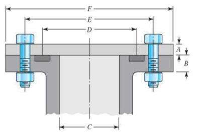
| Problem Number | 8-33 | 8-34 | 8-35 | 8-36 |
| A | 20 mm |
|
20 mm |
|
| B | 20 mm |
|
25 mm |
|
| C | 100 mm | 3.5 in | 0.8 m | 3.25 in |
| D | 150 mm | 4.25 in | 0.9 m | 3.5 in |
| E | 200 mm | 6 in | 1.0 m | 5.5 in |
| F | 300 mm | 8 in | 1.1 m | 7 in |
| N | 10 | 10 | 36 | 8 |
| pg | 6 MPa | 1500 psi | 550 kPa | 1200 psi |
| Bolt grade | ISO 9.8 | SAE 5 | ISO 10.9 | SAE 8 |
| Bolt spec. | M12 × 1.75 |
|
M10 × 1.5 |
|
The yield factor of safety
The load factor of safety.
The joint separation factor.
Answer to Problem 35P
The yield factor of safety is
The load factor of safety is
The joint separation factor is
Explanation of Solution
Write the expression of the length of the material squeeze between the bolt face and washer face.
Here the length of the material squeeze between the bolt face and washer face is
Write the expression for the length of the bolt.
Here the length of bolt is
Write the expression of the threaded length for hexagonal bolt.
Here the threaded length is
Write the expression of the length of the unthreaded portion in grip.
Here, the length of the unthreaded portion in the grip is
Write the expression of the length of the threaded portion in grip.
Here, the length of threaded portion in the grip is
Write the expression of the major area diameter.
Here the nominal diameter of the bolt is
Write the expression of the stiffness for the bolt.
Here the bolt stiffness is
Write the expression of stiffness for the steel cylinder.
Here the stiffness of the steel cylinder is
Write the expression for the midpoint of the complete joint.
Here, the midpoint of the joint is
Write the expression of the thickness of the upper frustum.
Here, the thickness of upper frustum of the gasket is
Write the expression for the effective sealing diameter of the gasket sealing in upper frustum.
Here, the effective sealing diameter of upper frustum of the gasket sealing is
Write the expression for the stiffness of the upper frustum of cast iron vessel.
Here, the stiffness of the cast-iron pressure vessel in the upper frustum is
Write the expression for the stiffness of the lower frustum of the cast iron vessel.
Here, the stiffness of the cast-iron pressure vessel in the lower frustum is
Write the expression for the stiffness of the member or assembly.
Here, the stiffness of the member is
Write the expression of joint constant.
Here the joint constant is
Write the expression of initial tension in the bolt.
Here the tensile stress area is
Write the expression of the effective area of the cylinder.
Here, the effective area of the cylinder is
Write the expression for the total force acting on the assembly.
Here, the total load acting on the assembly is
Write the expression for the load acting on each bolt.
Here, the number of bolt is
Write the expression for yield factor of safety.
Here the overload factor of safety is
Write the expression of overload factor of safety.
Here the overload factor of safety is
Write the expression of joint separation factor of safety.
Here the factor of safety based on joint separation is
Conclusion:
Substitute
Refer to Table
Substitute
Substitute
Substitute
Substitute
Substitute
Refer to Table
Substitute
Substitute
Substitute
Substitute
Substitute
Refer to Table
Substitute
Substitute
Substitute
Substitute
Refer to Table
Substitute
Substitute
Substitute
Substitute
Substitute
Thus, the yield factor of safety is
Substitute
Thus, the load factor of safety is
Substitute
Thus, the joint separation factor is
Want to see more full solutions like this?
Chapter 8 Solutions
Shigley's Mechanical Engineering Design (McGraw-Hill Series in Mechanical Engineering)


- A cap screw, ¾ in.-10-UNC-2, with a hexagonal head that is 9/16 in. thick, carries a tensile load of 3000 lb. If the material is AISI 1015, cold drawn, find the factor of safety based on ultimate strengths of a. the threaded shank, b. the head against being sheared off, and c. the bearing surface under the head. d. Is there any need to consider the strength of standard cap-screw heads in design?arrow_forwardA semi-elliptic spring used for automobile suspension, consists of two extra full-length leaves and eight graduated-length leaves, including the master leaf. The centre-to centre distance between the two eyes is 1 m. The leaves are made of steel 55Si2Mo90 (Syt = 1500 N/mm2and E = 207000 N/mm2) and the factor of safety is 2. The maximum spring load is 30 kN. The leaves are pre- stressed so as to equalize stresses in all leaves under maximum load. Determine the dimensions of the cross-section of the leaves and the deflection at the end of the spring.arrow_forwardA bushed pin type flexible coupling is used to transmit 10 kW power at 720 rpm. The design torque is 150% of rated torque. The keys have square cross-section. The permissible stresses are: For shaft and key material, τ = 66.67 N/mm2 , σc = 200 N/mm2 ; For pin material, τ = 35 N/mm2 , σt = 133 N/mm2 ; For flange material τ = 16.67 N/mm2 . The permissible bearing pressure for rubber bushes is 1 N/mm2. The number of bushes is 4. Design the bushed pin flexible coupling. Explain Axle, Spindle, Counter shaft and line-shaft with their examples .arrow_forward
- A bushed pin type flexible coupling is used to transmit 10 kW power at 720 rpm. The design torque is 150% of rated torque. The keys have square cross-section. The permissible stresses are: For shaft and key material, τ = 66.67 N/mm2, σc = 200 N/mm2; For pin material, τ = 35 N/mm2, σt = 133 N/mm2; For flange material τ = 16.67 N/mm2. The permissible bearing pressure for rubber bushes is 1 N/mm2. The number of bushes is 4. Design the bushed pin flexible coupling.arrow_forwardDetermine the safe tensile load for fine series bolts of (a) M 24and (b) M 38. Assume that the bolts are not initially stressed and take the safe tensile stress as 450MPa.arrow_forwardA rigid coupling with 30 inches of bolt circle diameter transmits a torque of 18,000 lb-in. The coupling material has a yield strength of 90,000 psi. The coupling is fastened by six bolts. Assume design factor of N=3 Calculate the diameter of each bolt.arrow_forward
- A mild steel shaft has to transmit 75 kW at 200 rpm. Design a cast Iron flange coupling for the shaft. The allowable stresses are Shear stress for the shaft and keys 40 N/mm²Shear stress for bolts = 28 N/mm²Shear stress for C.I. coupling = 20 N/mm² Take wearing stress as twice the shear stress value and number of bolts for coupling as 6.arrow_forward8. Design a clamp coupling for transmitting 25 kW at 300 rpm. Allowable shear stresses in shaft and key are 50 MPa and 45 MPa, respectively. The number of bolts joining the two halves of muff is 4. The permissible tensile stress in the bolt is 70 MPa and the permissible crushing stress in the key is 90 MPa. The coeffi cient of friction between the muff of the CI and the shaft of steel is 0.20.arrow_forwardA right angled bell crank lever is to be designed to raise a load of 5 kN at the short arm end. The lengths of short and long arms are 100 and 450 mm respectively. The lever and the pins are made of steel 30C8 (S = 400 N/mm2). And the factor of safety is 5.the permissible bearing pressure on the pin is 10 N/mm². The lever has a rectangular cross section and the ratio of width to thickness is 3:1. The length to diameter ratio of the fulcrum pin is 1.25:1. Calculate (i) The diameter and length of the fulcrum pin (ii) The dimensions of the cross section.arrow_forward
- A cylinder with a nominal 2.5 in ID, a 4.0 in OD, and a 3.0 in length is to be mated with a solid shaft with a nominal 2.5 in diameter. A medium drive fit is desired (as defined in Table 7-9). The cylinder and shaft are made from steel, with Sy = 100 kpsi and E = 30 Mpsi. The coefficient of friction for the steel interface is 0.7. a. Specify the maximum and minimum allowable diameters for both the cylinder hole and the shaft. b. Determine the torque that can be transmitted through this joint, assuming the shaft and cylinder are both manufactured within their tolerances such that the minimum interference is achieved. c. Suppose the shaft and cylinder are both manufactured within their tolerances such that the maximum interference is achieved. Check for yielding of the cylinder at its inner radius by finding the following: i. The pressure at the interface ii. The tangential and radial stresses in the cylinder, at its inner radius. iii. The factor of safety for static yielding of the…arrow_forwardDesign a cast iron type flange coupling to transmit 15 kW at 900 rpm from an electric motor to a compressor. Take shear stress for shaft, bolt and key material as 40 MPa.arrow_forwardPls give right answer with step by step explanation. Design a clamp coupling for a shaft diameter of 60 mm. The torsional moment to be transmitted by this coupling taking in to account over loading as 160 N-m. The number of bolts used are 6 and the allowable stress in the material of the bolt is limited to 5N / m * m ^ 2 . The coefficient of friction between the shaft and muff material is 0.25.arrow_forward
 Elements Of ElectromagneticsMechanical EngineeringISBN:9780190698614Author:Sadiku, Matthew N. O.Publisher:Oxford University Press
 Mechanics of Materials (10th Edition)Mechanical EngineeringISBN:9780134319650Author:Russell C. HibbelerPublisher:PEARSON
 Thermodynamics: An Engineering ApproachMechanical EngineeringISBN:9781259822674Author:Yunus A. Cengel Dr., Michael A. BolesPublisher:McGraw-Hill Education
 Control Systems EngineeringMechanical EngineeringISBN:9781118170519Author:Norman S. NisePublisher:WILEY
 Mechanics of Materials (MindTap Course List)Mechanical EngineeringISBN:9781337093347Author:Barry J. Goodno, James M. GerePublisher:Cengage Learning
 Engineering Mechanics: StaticsMechanical EngineeringISBN:9781118807330Author:James L. Meriam, L. G. Kraige, J. N. BoltonPublisher:WILEY