
Concept explainers
Videos
For the pressure cylinder defined in the problem specified in the table, the gas pressure is cycled between pg and pg/2. Determine the fatigue factor of safety for the bolts using the Goodman criterion.
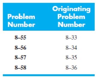
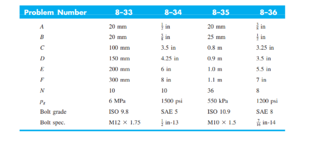
The figure illustrates the non-permanent connection of a steel cylinder head to a grade 30 castiron pressure vessel using N bolts. A confined gasket seal has an effective sealing diameter D. The cylinder stores gas at a maximum pressure pg. For the specifications given in the table for the specific problem assigned, select a suitable bolt length from the preferred sizes in Table A–17, then determine the yielding factor of safety np, the load factor nL, and the joint separation factor n0.
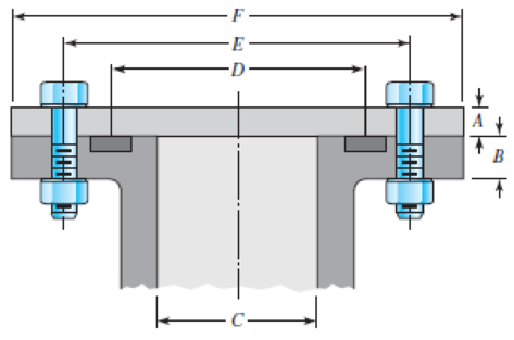
Problems 8–33 to 8–36
Want to see the full answer?
Check out a sample textbook solution
Chapter 8 Solutions
Shigley's Mechanical Engineering Design (McGraw-Hill Series in Mechanical Engineering)


- A bushed pin type flexible coupling is used to transmit 10 kW power at 720 rpm. The design torque is 150% of rated torque. The keys have square cross-section. The permissible stresses are: For shaft and key material, τ = 66.67 N/mm2 , σc = 200 N/mm2 ; For pin material, τ = 35 N/mm2 , σt = 133 N/mm2 ; For flange material τ = 16.67 N/mm2 . The permissible bearing pressure for rubber bushes is 1 N/mm2. The number of bushes is 4. Design the bushed pin flexible coupling. Explain Axle, Spindle, Counter shaft and line-shaft with their examples .arrow_forwardA bushed pin type flexible coupling is used to transmit 10 kW power at 720 rpm. The design torque is 150% of rated torque. The keys have square cross-section. The permissible stresses are: For shaft and key material, τ = 66.67 N/mm2, σc = 200 N/mm2; For pin material, τ = 35 N/mm2, σt = 133 N/mm2; For flange material τ = 16.67 N/mm2. The permissible bearing pressure for rubber bushes is 1 N/mm2. The number of bushes is 4. Design the bushed pin flexible coupling.arrow_forwardA helical compression spring has a scale of 500 lb/in., an outside diameter of 2.75 in, a free length of 8 inches and with squared and ground ends. The load is 1,000 lbs and the working stress on the wire material is 65000 psi. If the Wahl factor of 1.25 is to be used, calculate the following: A. The standard wire diameter B. The number of active coil if G = 10 800 000 psi C. The solid height D. The stress at solid heightarrow_forward
- A helical compression spring has a scale of 400 lbs/inch, an inside diameter of 2.5 inches, a free length of 8 inches and with squared and ground ends. Material is to be chrome vanadium steel. For a load P of 750 lbs and for the average service Determine the standard size wire diameter Determine the number of active coils Determine the solid height Determine the stress at solid heightarrow_forward3. Design a compression coupling for a shaft to transmit 1300 N-m. The allowable shear stress for the shaft and key is 40 MPa and the number of bolts connecting the two halves are 4. The permissible tensile stress for the bolts material is 70 MPa. The coefficient of friction between the muff and the shaft surface may be taken as 0.3.arrow_forwardCalculate the maximum tensile stress developed in a 1/4-20 bolt (Major dia = 0.2500" and Root dia = 0.1959"), 3" long, and a head height of 0.1875", if it is subjected to a load of 426 lbs.arrow_forward
- A band clutch has an angle of contact of 260 degrees on a 16 in diameter drum The rotational speed of the drum is 260 rpm and the clutch transmit 10 hp. The band is 1/16 - in. thick and has a designstress of 4800 psi. How wide should the band be?arrow_forwardThe shaft of a belt drive is made of AISI C1020 as rolled steel. The belt tensions vary continuously during transmission at a constant tension ratio of 3:1; the maximum tight side tension being 400 lb and the minimum tight side tension is expected to be 160 lb, at a pulley diameter of 12 inches. For a Goodman factor of safety of 1.8, recommend the diameter of the shaft. Consider a machined surface and the effect of a hardened profile keyway in the shaft.arrow_forwardThe figure shows a shaft mounted in bearings at A and D and having pulleys at B and C. The forces shown acting on the pulley surfaces represent the belt tensions. The shaft is to be made of AISI 1035 CD steel. The shaft is rotating at speed of 1000 rpm. Find the minimum factor of safety for fatigue based on infinite life. If the life is not infinite, estimate the number of cycles. Be sure to check for yielding. Take shaft diameter to be 1.5 inches.arrow_forward
- 5. Design a sleeve coupling for the transmission of 12 kW at 300 rpm by two connected steel shafts. Take service factor KS 1.25. The sleeve is made of CI. The key and the shaft are made of the same material. Allowable stress: Shear stresses in key and shaft 50 MPa Crushing stress in key= 100 MPa Shear stress in CI sleeve = 10 MPaarrow_forwardUsing safety factor of (3) , determine a minimum diameter for the shaft shown in FIGURE 2. The shaft material AISI 1050 HR ( hot rolled ) steel . The power to be transmitted is (8 KW) at ( 900 rpm). The diameter of the pulley is (250 mm ) and the ratio of belt tensions is (2.5 ). (90 percent ) reliability is desired.arrow_forward6. Design a clamp coupling for transmitting 36 kW, at 200 rpm. Allowable shear stress in shaft is 45 MPa, allowable shear stress in key is 40 MPa, and allowable crushing stress in key is 90 MPa. The number of bolts joining the two halves is 4. The permissible tensile stress in bolts is 60 MPa. The coefficient of friction between the muff and shaft can be taken as 0.25arrow_forward
 Elements Of ElectromagneticsMechanical EngineeringISBN:9780190698614Author:Sadiku, Matthew N. O.Publisher:Oxford University Press
 Mechanics of Materials (10th Edition)Mechanical EngineeringISBN:9780134319650Author:Russell C. HibbelerPublisher:PEARSON
 Thermodynamics: An Engineering ApproachMechanical EngineeringISBN:9781259822674Author:Yunus A. Cengel Dr., Michael A. BolesPublisher:McGraw-Hill Education
 Control Systems EngineeringMechanical EngineeringISBN:9781118170519Author:Norman S. NisePublisher:WILEY
 Mechanics of Materials (MindTap Course List)Mechanical EngineeringISBN:9781337093347Author:Barry J. Goodno, James M. GerePublisher:Cengage Learning
 Engineering Mechanics: StaticsMechanical EngineeringISBN:9781118807330Author:James L. Meriam, L. G. Kraige, J. N. BoltonPublisher:WILEY