
Concept explainers
Videos
8–37 to
8–40 Repeat the requirements for the problem specified in the table if the bolts and nuts are replaced with cap screws that are threaded into tapped holes in the cast-iron cylinder.
| Problem Number | Originating Problem Number |
| 8–37 | 8–33 |
| 8–38 | 8–34 |
| 8–39 | 8–35 |
| 8–40 | 8–36 |
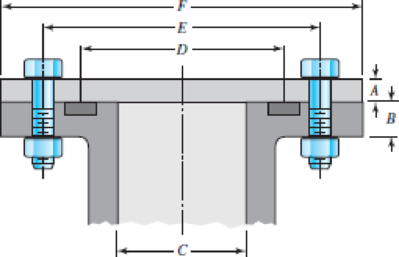
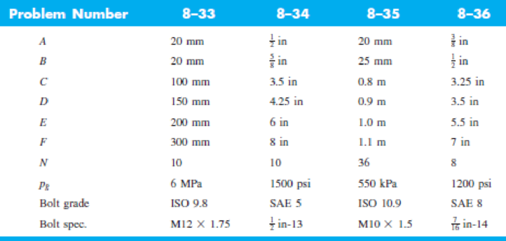
8–33 to
8–36 The figure illustrates the non-permanent connection of a steel cylinder head to a grade 30 castiron pressure vessel using N bolts. A confined gasket seal has an effective sealing diameter D. The cylinder stores gas at a maximum pressure pg. For the specifications given in the table for the specific problem assigned, select a suitable bolt length from the preferred sizes in Table A–17, then determine the yielding factor of safety np, the load factor nL, and the joint separation factor n0.
Repeat the requirements for the problem specified in the table if the bolts and nuts are replaced with cap screws that are threaded into tapped holes in the cast-iron cylinder.
Want to see the full answer?
Check out a sample textbook solution
Chapter 8 Solutions
Shigley's Mechanical Engineering Design (McGraw-Hill Series in Mechanical Engineering)


- Information about the clamp assembly in the figure is given below. Thread diameter 12 mm, root diameter 10.16 mm, pitch 1.5 mm, screw profile angle 2α=60, friction surface of table A diameter 10 mm, friction between plate A-screw end surface coefficient 0.15 and screw-nut friction coefficient 0.15 is given. If a hand force of 200N is applied to the vise arm, if applied, a) How much force is applied to the clamped part. b) Calculate the efficiency of the vise.arrow_forwardThe layout of transmission shaft carrying two pulleys B and C and supported on bearings A and D is shown in Figure below. Power is supplied to the shaft by means of a vertical belt on pulley B, that is then transmitted to pulley C carrying a horizontal belt. The maximum tension in belt on pulley B is 2.5 kN. The angle of wrap for both the pulleys is 180o and the coefficient of friction 0.24. The shaft is made of plain carbon steel 30C8 (Syt=400 N/mm2) and the factor of safety is 3. Determine the shaft diameter on strength basis.arrow_forwardA cylinder with a nominal 2.5 in ID, a 4.0 in OD, and a 3.0 in length is to be mated with a solid shaft with a nominal 2.5 in diameter. A medium drive fit is desired (as defined in Table 7-9). The cylinder and shaft are made from steel, with Sy = 100 kpsi and E = 30 Mpsi. The coefficient of friction for the steel interface is 0.7. a. Specify the maximum and minimum allowable diameters for both the cylinder hole and the shaft. b. Determine the torque that can be transmitted through this joint, assuming the shaft and cylinder are both manufactured within their tolerances such that the minimum interference is achieved. c. Suppose the shaft and cylinder are both manufactured within their tolerances such that the maximum interference is achieved. Check for yielding of the cylinder at its inner radius by finding the following: i. The pressure at the interface ii. The tangential and radial stresses in the cylinder, at its inner radius. iii. The factor of safety for static yielding of the…arrow_forward
- An oval profile straightening machine is shown in the adjacent figure. The movement bolt in the mechanism is single-ended, 80mm diameter and 10mm. It has a square screw with a step. Tightening the movement bolt to the profile An axial force of 10 kN is required as a force. The average diameter between the handle and the bolt is 60 mm. with bolt The friction coefficient between the nut and bolt and the handle is 0.12. The length of the force arm is given as 500 mm. i) Applying the bolt to the lever to apply the desired axial load Find the required force. ii) Find the efficiency of the mechanism. iii) Checking the bolt's security taking into account the A-A cross-section Please pay. Yield strength of bolt Syield strenght= 420 MPaarrow_forwardA mild steel shaft has to transmit 75 kW at 200 rpm. Design a cast Iron flange coupling for the shaft. The allowable stresses are Shear stress for the shaft and keys 40 N/mm²Shear stress for bolts = 28 N/mm²Shear stress for C.I. coupling = 20 N/mm² Take wearing stress as twice the shear stress value and number of bolts for coupling as 6.arrow_forwardThe worm shaft shown in the figure transmits 1-kW at 500 rev/min. A static forceanalysis results are also shown in the figure. Bearing A is to be an angular-contact ballbearing mounted to take the 2.75 kN thrust load. The bearing at B is to take only theradial load, so a straight roller bearing will be employed. Use an application factor of1.2, a desired life of 25 kh, and a combined reliability goal of 0.99. (a)Specify each bearing by giving all required charecteristics. (b) Determine the radial and thrust components of loads on each bearing. (c) Make a design assessment for each bearing and of the system.arrow_forward
- The figure shows a shaft mounted in bearings at A and D and having pulleys at B and C. The forces shown acting on the pulley surfaces represent the belt tensions. The shaft is to be made of AISI 1035 CD steel. The shaft is rotating at speed of 1000 rpm. Find the minimum factor of safety for fatigue based on infinite life. If the life is not infinite, estimate the number of cycles. Be sure to check for yielding. Take shaft diameter to be 1.5 inches.arrow_forward6. Design a clamp coupling for transmitting 36 kW, at 200 rpm. Allowable shear stress in shaft is 45 MPa, allowable shear stress in key is 40 MPa, and allowable crushing stress in key is 90 MPa. The number of bolts joining the two halves is 4. The permissible tensile stress in bolts is 60 MPa. The coefficient of friction between the muff and shaft can be taken as 0.25arrow_forward(4) A single square-thread power screw has an input power of 3.0kW at a speed of 1 rev/s. The screw has a major diameter of 36mm and a pitch of 6mm. The frictional coefficients are 0.14 for the threads and 0.09 for the collar, with a collar friction radius of 45mm. Find: (a) the axial resisting load F (b) the combined efficiency of the screw and collar;arrow_forward
- In the figure below the clamping force on the pipe is (331.7 lb), knowing that a single threaded screw Acme with major diameter (1 in) is used with coefficient of friction (0.2135). If booth screw and nut are made from 1030 - hot rolled Carbon Steel. Determine: 1- The tightening and loosening torques. 2- Thread screw and nut shear safety factors in case of double threads are in engagement. 3.3 in 2 7.2 in 32 3 in hingearrow_forwardDesign a rigid flange coupling to transmit a torque of 257N-m between two coaxial shafts. The shaft is made of alloy steel, flanges out of cast iron and bolts out of steel. Four bolts are used to couple the flanges. The shafts are keyed to the flange hub. The permissible stresses are given below: Shear stress on shaft =100MPa Bearing or crushing stress on shaft =250MPa Shear stress on keys =100MPa Bearing stress on keys = 250MPa Shearing stress on cast iron = 200Mpa Shear stress on bolts =100MPa Answer in Word pleasearrow_forwardThe figure gives the cross-section of a grade 25 cast-iron pressure vessel. A total of N bolts are to be used to resist a separating force of 150 kN. (a) Determine kb, km, and C. (b) Find the number of bolts required for a load factor of 2 where the bolts may be reused when the joint is taken apart. (c) With the number of bolts obtained in part (b), determine the realized load factor for overload, the yielding factor of safety, and the load factor for joint separation. Use (SI) units as it appliesarrow_forward
 Mechanics of Materials (MindTap Course List)Mechanical EngineeringISBN:9781337093347Author:Barry J. Goodno, James M. GerePublisher:Cengage Learning