
Shigley's Mechanical Engineering Design (McGraw-Hill Series in Mechanical Engineering)
10th Edition
ISBN: 9780073398204
Author: Richard G Budynas, Keith J Nisbett
Publisher: McGraw-Hill Education
expand_more
expand_more
format_list_bulleted
Videos
Textbook Question
Chapter 8, Problem 26P
A
Problem 8-26
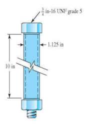
- (a) Determine the bolt stiffness, the tube stiffness, and the joint constant C.
- (b) When the one-third turn-of-nut is applied, what is the initial tension Fi in the bolt?
Expert Solution & Answer
Want to see the full answer?
Check out a sample textbook solution
Students have asked these similar questions
The figure illustrates the connection of a steel cylinder head to a grade 30 cast-iron pressure vessel using N bolts. A confined gasket seal has an effective sealing diameter D. The cylinder stores gas at a maximum pressure pg. For the specifications given in the table for the specific problem assigned, select a suitable bolt length from the preferred sizes in Table A–17, then determine the yielding factor of safety np, the load factor nL, and the joint separation factor n0. See problem number 8-36, and please use the FEA exponential curve-fit for member stiffness.
(7) The cylinder head of a 10”x18” refrigerant compressor is attached by 10 stud bolts made of SAE
grade 5. The maximum cylinder pressure is 350psi.
(a) What size of bolt is to be used?
(b) What approximate tightening torque should be applied to induce a tightening stress of 0.9 time
of the proof stress?
A rigid coupling with 30 inches of bolt circle diameter transmits a torque of 18,000 lb-in. The coupling material has a yield strength of 90,000 psi. The coupling is fastened by six bolts. Assume design factor of N=3
Calculate the diameter of each bolt.
Chapter 8 Solutions
Shigley's Mechanical Engineering Design (McGraw-Hill Series in Mechanical Engineering)
Ch. 8 - A power screw is 25 mm in diameter and has a...Ch. 8 - Using the information in the footnote of Table...Ch. 8 - Show that for zero collar friction the efficiency...Ch. 8 - A single-threaded power screw is 25 mm in diameter...Ch. 8 - The machine shown in the figure can be used for a...Ch. 8 - The press shown for Prob. 8-5 has a rated load of...Ch. 8 - For the screw clamp shown, a force is applied at...Ch. 8 - The C clamp shown in the figure for Prob. 8-7 uses...Ch. 8 - Find the power required to drive a 1.5-in power...Ch. 8 - A single square-thread power screw has an input...
Ch. 8 - Prob. 11PCh. 8 - An M14 2 hex-head bolt with a nut is used to...Ch. 8 - Prob. 13PCh. 8 - A 2-in steel plate and a 1-in cast-iron plate are...Ch. 8 - Repeat Prob. 8-14 with the addition of one 12 N...Ch. 8 - A 2-in steel plate and a 1-in cast-iron plate are...Ch. 8 - Two identical aluminum plates are each 2 in thick,...Ch. 8 - Prob. 18PCh. 8 - A 30-mm thick AISI 1020 steel plate is sandwiched...Ch. 8 - Prob. 20PCh. 8 - Prob. 21PCh. 8 - Prob. 22PCh. 8 - A 2-in steel plate and a 1-in cast-iron plate are...Ch. 8 - An aluminum bracket with a 12-in thick flange is...Ch. 8 - An M14 2 hex-head bolt with a nut is used to...Ch. 8 - A 34 in-16 UNF series SAE grade 5 bolt has a 34-in...Ch. 8 - From your experience with Prob. 8-26, generalize...Ch. 8 - Prob. 28PCh. 8 - Prob. 29PCh. 8 - Prob. 30PCh. 8 - For a bolted assembly with eight bolts, the...Ch. 8 - Prob. 32PCh. 8 - 8-33 to 8-36 The figure illustrates the...Ch. 8 - 8-33 to 8-36 The figure illustrates the...Ch. 8 - 8-33 to 8-36 The figure illustrates the...Ch. 8 - 8-33 to 8-36 The figure illustrates the...Ch. 8 - Prob. 37PCh. 8 - Prob. 38PCh. 8 - 837 to 840 Repeat the requirements for the problem...Ch. 8 - Prob. 40PCh. 8 - 841 to 844 For the pressure vessel defined in the...Ch. 8 - Prob. 42PCh. 8 - Prob. 43PCh. 8 - Prob. 44PCh. 8 - Bolts distributed about a bolt circle are often...Ch. 8 - The figure shows a cast-iron bearing block that is...Ch. 8 - Prob. 47PCh. 8 - Prob. 48PCh. 8 - Prob. 49PCh. 8 - Prob. 50PCh. 8 - 851 to 854 For the pressure cylinder defined in...Ch. 8 - Prob. 52PCh. 8 - 851 to 854 For the pressure cylinder defined in...Ch. 8 - 851 to 854 For the pressure cylinder defined in...Ch. 8 - 855 to 858 For the pressure cylinder defined in...Ch. 8 - 855 to 858 For the pressure cylinder defined in...Ch. 8 - 855 to 858 For the pressure cylinder defined in...Ch. 8 - For the pressure cylinder defined in the problem...Ch. 8 - A 1-in-diameter hot-rolled AISI 1144 steel rod is...Ch. 8 - The section of the sealed joint shown in the...Ch. 8 - Prob. 61PCh. 8 - Prob. 62PCh. 8 - Prob. 63PCh. 8 - Prob. 64PCh. 8 - Using the Goodman fatigue criterion, repeat Prob....Ch. 8 - The figure shows a bolted lap joint that uses SAE...Ch. 8 - Prob. 67PCh. 8 - A bolted lap joint using ISO class 5.8 bolts and...Ch. 8 - Prob. 69PCh. 8 - The figure shows a connection that employs three...Ch. 8 - A beam is made up by bolting together two cold...Ch. 8 - Prob. 72PCh. 8 - Prob. 73PCh. 8 - Prob. 74PCh. 8 - A vertical channel 152 76 (see Table A7) has a...Ch. 8 - The cantilever bracket is bolted to a column with...Ch. 8 - Prob. 77PCh. 8 - The figure shows a welded fitting which has been...Ch. 8 - Prob. 79PCh. 8 - Prob. 80PCh. 8 - Prob. 81P
Knowledge Booster


Learn more about
Need a deep-dive on the concept behind this application? Look no further. Learn more about this topic, mechanical-engineering and related others by exploring similar questions and additional content below.Similar questions
- A cap screw, ¾ in.-10-UNC-2, with a hexagonal head that is 9/16 in. thick, carries a tensile load of 3000 lb. If the material is AISI 1015, cold drawn, find the factor of safety based on ultimate strengths of a. the threaded shank, b. the head against being sheared off, and c. the bearing surface under the head. d. Is there any need to consider the strength of standard cap-screw heads in design?arrow_forwardA cap screw, ¾ in.-10-UNC-2, with a hexagonal head that is 9/16 in. thick, carries a tensile load of 3000 lb. If the material is AISI 1015, cold drawn, find the factor of safety based on ultimate strengths of a.the threaded shank, b.the head against being sheared off, and c.the bearing surface under the head. d.Is there any need to consider the strength of standard cap-screw heads in design?arrow_forwardFigure 8-19 is a cross-section of ASTM A36. A total of N bolts are to be used to resist a separating force of 7258.97N is one bolt. A) Determine kb,km, and C B) Determine the realized load factor for overload, the yielding factor of safety, and the load factor of joint separation.arrow_forward
- Pls give right answer with step by step explanation. Design a clamp coupling for a shaft diameter of 60 mm. The torsional moment to be transmitted by this coupling taking in to account over loading as 160 N-m. The number of bolts used are 6 and the allowable stress in the material of the bolt is limited to 5N / m * m ^ 2 . The coefficient of friction between the shaft and muff material is 0.25.arrow_forwardThe crank of jib crane model J-06T is fixed at one end and hinged to a pivot pin. The crank is 300 in and 5” in diameter. Assuming carbon –alloy steel (E = 29,000 ksi) What is the safe working compressive load on the crank at FS = 4?arrow_forward3. Design a compression coupling for a shaft to transmit 1300 N-m. The allowable shear stress for the shaft and key is 40 MPa and the number of bolts connecting the two halves are 4. The permissible tensile stress for the bolts material is 70 MPa. The coefficient of friction between the muff and the shaft surface may be taken as 0.3.arrow_forward
- A cylinder with a nominal 2.5 in ID, a 4.0 in OD, and a 3.0 in length is to be mated with a solid shaft with a nominal 2.5 in diameter. A medium drive fit is desired (as defined in Table 7-9). The cylinder and shaft are made from steel, with Sy = 100 kpsi and E = 30 Mpsi. The coefficient of friction for the steel interface is 0.7. a. Specify the maximum and minimum allowable diameters for both the cylinder hole and the shaft. b. Determine the torque that can be transmitted through this joint, assuming the shaft and cylinder are both manufactured within their tolerances such that the minimum interference is achieved. c. Suppose the shaft and cylinder are both manufactured within their tolerances such that the maximum interference is achieved. Check for yielding of the cylinder at its inner radius by finding the following: i. The pressure at the interface ii. The tangential and radial stresses in the cylinder, at its inner radius. iii. The factor of safety for static yielding of the…arrow_forwardA semi-elliptic spring used for automobile suspension, consists of two extra full-length leaves and eight graduated-length leaves, including the master leaf. The centre-to centre distance between the two eyes is 1 m. The leaves are made of steel 55Si2Mo90 (Syt = 1500 N/mm2and E = 207000 N/mm2) and the factor of safety is 2. The maximum spring load is 30 kN. The leaves are pre- stressed so as to equalize stresses in all leaves under maximum load. Determine the dimensions of the cross-section of the leaves and the deflection at the end of the spring.arrow_forwardInformation about the clamp assembly in the figure is given below. Thread diameter 12 mm, root diameter 10.16 mm, pitch 1.5 mm, screw profile angle 2α=60, friction surface of table A diameter 10 mm, friction between plate A-screw end surface coefficient 0.15 and screw-nut friction coefficient 0.15 is given. If a hand force of 200N is applied to the vise arm, if applied, a) How much force is applied to the clamped part. b) Calculate the efficiency of the vise.arrow_forward
- Design a rigid flange coupling to transmit a torque of 250N-m between two coaxial shafts. The shaft is made of alloy steel, flanges out of cast iron and bolts out of steel. Four bolts are used to couple the flanges. The shafts are keyed to the flange hub. The permissible stresses are given below: Shear stress on shaft =100MPa Bearing or crushing stress on shaft =250MPa Shear stress on keys =100MPa Bearing stress on keys = 250MPa Shearing stress on cast iron = 200Mpa Shear stress on bolts =100MPa Torque = 257N-marrow_forwardRepeat Prob. 15-7 if the dead load reaction is 80 k and the live load reaction is 110 k, and if 1-in A325-N bolts and A572 steel ( Fy = 50 ksi and Fu = 65 ksi ) are to be used. Prob. 15-7: Design a framed beam connection for a W18 x 50 to support a dead load reaction of 30 k and a live load reaction of 20 k, using the LRFD and ASD methods.The beam’s top flange is to be coped for a 2-in depth, and 7/8-in A325-X bolts in standard-size holes are to be used.The beam is connected to a W27 x 146 girder. Connection is A36,while W shapes are A992arrow_forwardDesign a rigid flange coupling to transmit a torque of 257N-m between two coaxial shafts. The shaft is made of alloy steel, flanges out of cast iron and bolts out of steel. Four bolts are used to couple the flanges. The shafts are keyed to the flange hub. The permissible stresses are given below: Shear stress on shaft =100MPa Bearing or crushing stress on shaft =250MPa Shear stress on keys =100MPa Bearing stress on keys = 250MPa Shearing stress on cast iron = 200Mpa Shear stress on bolts =100MPa Answer in Word pleasearrow_forward
arrow_back_ios
SEE MORE QUESTIONS
arrow_forward_ios
Recommended textbooks for you
 Mechanics of Materials (MindTap Course List)Mechanical EngineeringISBN:9781337093347Author:Barry J. Goodno, James M. GerePublisher:Cengage Learning
Mechanics of Materials (MindTap Course List)
Mechanical Engineering
ISBN:9781337093347
Author:Barry J. Goodno, James M. Gere
Publisher:Cengage Learning
Mechanical SPRING DESIGN Strategy and Restrictions in Under 15 Minutes!; Author: Less Boring Lectures;https://www.youtube.com/watch?v=dsWQrzfQt3s;License: Standard Youtube License