
Shigley's Mechanical Engineering Design (McGraw-Hill Series in Mechanical Engineering)
10th Edition
ISBN: 9780073398204
Author: Richard G Budynas, Keith J Nisbett
Publisher: McGraw-Hill Education
expand_more
expand_more
format_list_bulleted
Videos
Textbook Question
Chapter 8, Problem 76P
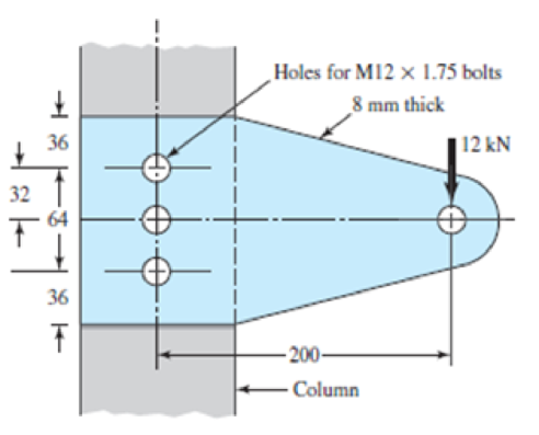
The cantilever bracket is bolted to a column with three M12 × 1.75 ISO 5.8 bolts. The bracket is made from AISI 1020 hot-rolled steel. Assume the bolt threads do not extend into the joint. Find the factors of safety for the following failure modes: shear of bolls, bearing of bolts, bearing of bracket, and bending of bracket.
Problem 8–76
Dimensions in millimeters.
Expert Solution & Answer
Want to see the full answer?
Check out a sample textbook solution
Students have asked these similar questions
A semi-elliptic spring used for automobile suspension, consists of two extra full-length leaves and eight graduated-length leaves, including the master leaf. The centre-to centre distance between the two eyes is 1 m. The leaves are made of steel 55Si2Mo90 (Syt = 1500 N/mm2and E = 207000 N/mm2) and the factor of safety is 2. The maximum spring load is 30 kN. The leaves are pre- stressed so as to equalize stresses in all leaves under maximum load. Determine the dimensions of the cross-section of the leaves and the deflection at the end of the spring.
The rotating shaft running at n = 900 rpm, shown in the figure below, is machined from AISI 1045 CD steel. It is subjected to a force of F = 10.1 kN. The shaft is experiencing an operating temperature of 35 oC. With the specified loading and for the reliability of 99.9 %,
Determine the minimum factor of safety for fatigue based on infinite life*.
Determine the maximum safe load (Fmax) that can be applied for a factor of safety of 1.5 and a design life of 5x10⁵ cycles, all other input values remaining the same.
Determine the factor of safety against yielding.
The figure illustrates the connection of a steel cylinder head to a grade 30 cast-iron pressure vessel using N bolts. A confined gasket seal has an effective sealing diameter D. The cylinder stores gas at a maximum pressure pg. For the specifications given in the table for the specific problem assigned, select a suitable bolt length from the preferred sizes in Table A–17, then determine the yielding factor of safety np, the load factor nL, and the joint separation factor n0. See problem number 8-36, and please use the FEA exponential curve-fit for member stiffness.
Chapter 8 Solutions
Shigley's Mechanical Engineering Design (McGraw-Hill Series in Mechanical Engineering)
Ch. 8 - A power screw is 25 mm in diameter and has a...Ch. 8 - Using the information in the footnote of Table...Ch. 8 - Show that for zero collar friction the efficiency...Ch. 8 - A single-threaded power screw is 25 mm in diameter...Ch. 8 - The machine shown in the figure can be used for a...Ch. 8 - The press shown for Prob. 8-5 has a rated load of...Ch. 8 - For the screw clamp shown, a force is applied at...Ch. 8 - The C clamp shown in the figure for Prob. 8-7 uses...Ch. 8 - Find the power required to drive a 1.5-in power...Ch. 8 - A single square-thread power screw has an input...
Ch. 8 - Prob. 11PCh. 8 - An M14 2 hex-head bolt with a nut is used to...Ch. 8 - Prob. 13PCh. 8 - A 2-in steel plate and a 1-in cast-iron plate are...Ch. 8 - Repeat Prob. 8-14 with the addition of one 12 N...Ch. 8 - A 2-in steel plate and a 1-in cast-iron plate are...Ch. 8 - Two identical aluminum plates are each 2 in thick,...Ch. 8 - Prob. 18PCh. 8 - A 30-mm thick AISI 1020 steel plate is sandwiched...Ch. 8 - Prob. 20PCh. 8 - Prob. 21PCh. 8 - Prob. 22PCh. 8 - A 2-in steel plate and a 1-in cast-iron plate are...Ch. 8 - An aluminum bracket with a 12-in thick flange is...Ch. 8 - An M14 2 hex-head bolt with a nut is used to...Ch. 8 - A 34 in-16 UNF series SAE grade 5 bolt has a 34-in...Ch. 8 - From your experience with Prob. 8-26, generalize...Ch. 8 - Prob. 28PCh. 8 - Prob. 29PCh. 8 - Prob. 30PCh. 8 - For a bolted assembly with eight bolts, the...Ch. 8 - Prob. 32PCh. 8 - 8-33 to 8-36 The figure illustrates the...Ch. 8 - 8-33 to 8-36 The figure illustrates the...Ch. 8 - 8-33 to 8-36 The figure illustrates the...Ch. 8 - 8-33 to 8-36 The figure illustrates the...Ch. 8 - Prob. 37PCh. 8 - Prob. 38PCh. 8 - 837 to 840 Repeat the requirements for the problem...Ch. 8 - Prob. 40PCh. 8 - 841 to 844 For the pressure vessel defined in the...Ch. 8 - Prob. 42PCh. 8 - Prob. 43PCh. 8 - Prob. 44PCh. 8 - Bolts distributed about a bolt circle are often...Ch. 8 - The figure shows a cast-iron bearing block that is...Ch. 8 - Prob. 47PCh. 8 - Prob. 48PCh. 8 - Prob. 49PCh. 8 - Prob. 50PCh. 8 - 851 to 854 For the pressure cylinder defined in...Ch. 8 - Prob. 52PCh. 8 - 851 to 854 For the pressure cylinder defined in...Ch. 8 - 851 to 854 For the pressure cylinder defined in...Ch. 8 - 855 to 858 For the pressure cylinder defined in...Ch. 8 - 855 to 858 For the pressure cylinder defined in...Ch. 8 - 855 to 858 For the pressure cylinder defined in...Ch. 8 - For the pressure cylinder defined in the problem...Ch. 8 - A 1-in-diameter hot-rolled AISI 1144 steel rod is...Ch. 8 - The section of the sealed joint shown in the...Ch. 8 - Prob. 61PCh. 8 - Prob. 62PCh. 8 - Prob. 63PCh. 8 - Prob. 64PCh. 8 - Using the Goodman fatigue criterion, repeat Prob....Ch. 8 - The figure shows a bolted lap joint that uses SAE...Ch. 8 - Prob. 67PCh. 8 - A bolted lap joint using ISO class 5.8 bolts and...Ch. 8 - Prob. 69PCh. 8 - The figure shows a connection that employs three...Ch. 8 - A beam is made up by bolting together two cold...Ch. 8 - Prob. 72PCh. 8 - Prob. 73PCh. 8 - Prob. 74PCh. 8 - A vertical channel 152 76 (see Table A7) has a...Ch. 8 - The cantilever bracket is bolted to a column with...Ch. 8 - Prob. 77PCh. 8 - The figure shows a welded fitting which has been...Ch. 8 - Prob. 79PCh. 8 - Prob. 80PCh. 8 - Prob. 81P
Knowledge Booster


Learn more about
Need a deep-dive on the concept behind this application? Look no further. Learn more about this topic, mechanical-engineering and related others by exploring similar questions and additional content below.Similar questions
- A mild steel shaft has to transmit 75 kW at 200 rpm. Design a cast Iron flange coupling for the shaft. The allowable stresses are Shear stress for the shaft and keys 40 N/mm²Shear stress for bolts = 28 N/mm²Shear stress for C.I. coupling = 20 N/mm² Take wearing stress as twice the shear stress value and number of bolts for coupling as 6.arrow_forwardA 0.5-in.-diameter steel [E= 30,000 ksi] bolt (1) is placed in a copper tube (2). The copper [E= 16,000 ksi] tube has an outside diameter of 1.00 in., a wall thickness of 0.125 in., and a length of L= 8.0 in. Rigid washers, each with a thickness of t= 0.125 in., cap the ends of the copper tube. The bolt has 20 threads per inch. This means that each time the nut is turned one complete revolution, the nut advances 0.05 in. (i.e., 1/20 in.). The nut is hand-tightened on the bolt until the bolt, nut, washers, and tube are just snug, meaning that all slack has been removed from the assembly but no stress has yet been induced. What stresses are produced in the bolt and in the tube if the nut is tightened an additional quarter turn past the snug-tight condition?arrow_forwardA rigid coupling with 30 inches of bolt circle diameter transmits a torque of 18,000 lb-in. The coupling material has a yield strength of 90,000 psi. The coupling is fastened by six bolts. Assume design factor of N=3 Calculate the diameter of each bolt.arrow_forward
- Torque in = 40nm Holding torque out = 896nm 8.Using your answers from the gear box above, and given that the input shaft has a diameter of 12 mm and the output shaft has a diameter of 15 mm, both shafts are made from aluminium. When this transmission system was operated, it failed. Identify the position where the failure occurred and the reason for this failure. Suggests improvements to the system to overcome the failure mode. The shear strength of aluminium is 207 MPa.arrow_forwardThe figure gives the cross-section of a grade 25 cast-iron pressure vessel. A total of N bolts are to be used to resist a separating force of 150 kN. (a) Determine kb, km, and C. (b) Find the number of bolts required for a load factor of 2 where the bolts may be reused when the joint is taken apart. (c) With the number of bolts obtained in part (b), determine the realized load factor for overload, the yielding factor of safety, and the load factor for joint separation. Use (SI) units as it appliesarrow_forwardUsing safety factor of (3) , determine a minimum diameter for the shaft shown in FIGURE 2. The shaft material AISI 1050 HR ( hot rolled ) steel . The power to be transmitted is (8 KW) at ( 900 rpm). The diameter of the pulley is (250 mm ) and the ratio of belt tensions is (2.5 ). (90 percent ) reliability is desired.arrow_forward
- A motor is to transmit 150 kW to a piece of mechanical equipment. The power is transmitted through a solid structural steel shaft. Failure is by yielding, and the factor of safety is 1.25. The designer has the freedom to operate the motor at 60 rpm or 6000 rpm. For each case, determine the minimum shaft diameter. Shafts are available with diameters in increments of 5 mm. If weight is important, which speed would be used?arrow_forwardA rotating shaft of 40×4 mm AISI 1018 cold-drawn steel tubing has a 6 mm diameter hole drilled transversely through it. Estimate the factor of safety guarding against fatigue and static failures using the Gerber and Langer failure criteria for the following loading conditions: a. The shaft is subjected to a completely reversed torque of 120 N.m in phase with a completely reversed bending moment of 150 N.m. b. The shaft is subjected to a pulsating torque fluctuating from 20 to 160 N.m and as steady bending moment of 150 N.m.arrow_forwardDraw FBD and determine Stress and Safety Factor of Bicycle Axle (Thru Axel) Specification Weight of cyclist = 120 kg. Materials: Aluminum alloy (AL 6061-T6) Dimension: Length = 122 mm, Diameter = 12 mm, Thread pitch = 1.75 mm, Thread Length = 16 mm.arrow_forward
- In the Bolted Connection shown, find the following by ASD.Specifications:M20 Bolts in standard holes. Nominal hole diameter = 22mmEffective Hole diameter = nominal hole diameter + 2 mmA325 steel boltAssume thread in shear planeFv = 372 MPaProperties of Angle Bar< 125 x 125 x 13 mmA = 3065 mm²x = 36.3 mmy = 36.3 mmFy = 248 MPa , Fu = 410 MPa 1. For angle bars used as bolted tension element connected to another element only on one leg, the effective area Ae = UAn. Where: An = Net area, U = Shear lag factor = 1 – x/L, L= center to center longitudinal distance of extremely located fasteners, X= distance from centroid of angle bar to surface of contact of joined elements. What is the shear lag factor of our angular bar? a. 0.454 b. 0.9 c. 0.838 d. 0.869 2. Considering RUPTURE of angle bar, what is the allowable force P that the connection can handle if allowable RUPTURE stress in net area of angle bar is Fu/2 a. 463.83 kN…arrow_forwardA rectangular bar is cut from an AISI 1018 cold-drawn steel flat. The bar is 1 in wide by 3/8 in thick and has a ¼ in-diameter hole drilled through the center. The bar is subjected to a tension load fluctuating between 800 and 3000 lb. estimate the factors of safety guarding against failure by yielding and by fatigue action. (Assume infinite life is desire)arrow_forward3. Design a compression coupling for a shaft to transmit 1300 N-m. The allowable shear stress for the shaft and key is 40 MPa and the number of bolts connecting the two halves are 4. The permissible tensile stress for the bolts material is 70 MPa. The coefficient of friction between the muff and the shaft surface may be taken as 0.3.arrow_forward
arrow_back_ios
SEE MORE QUESTIONS
arrow_forward_ios
Recommended textbooks for you
 Elements Of ElectromagneticsMechanical EngineeringISBN:9780190698614Author:Sadiku, Matthew N. O.Publisher:Oxford University Press
 Mechanics of Materials (10th Edition)Mechanical EngineeringISBN:9780134319650Author:Russell C. HibbelerPublisher:PEARSON
 Thermodynamics: An Engineering ApproachMechanical EngineeringISBN:9781259822674Author:Yunus A. Cengel Dr., Michael A. BolesPublisher:McGraw-Hill Education
 Control Systems EngineeringMechanical EngineeringISBN:9781118170519Author:Norman S. NisePublisher:WILEY
 Mechanics of Materials (MindTap Course List)Mechanical EngineeringISBN:9781337093347Author:Barry J. Goodno, James M. GerePublisher:Cengage Learning
 Engineering Mechanics: StaticsMechanical EngineeringISBN:9781118807330Author:James L. Meriam, L. G. Kraige, J. N. BoltonPublisher:WILEY
Elements Of Electromagnetics
Mechanical Engineering
ISBN:9780190698614
Author:Sadiku, Matthew N. O.
Publisher:Oxford University Press
Mechanics of Materials (10th Edition)
Mechanical Engineering
ISBN:9780134319650
Author:Russell C. Hibbeler
Publisher:PEARSON
Thermodynamics: An Engineering Approach
Mechanical Engineering
ISBN:9781259822674
Author:Yunus A. Cengel Dr., Michael A. Boles
Publisher:McGraw-Hill Education
Control Systems Engineering
Mechanical Engineering
ISBN:9781118170519
Author:Norman S. Nise
Publisher:WILEY
Mechanics of Materials (MindTap Course List)
Mechanical Engineering
ISBN:9781337093347
Author:Barry J. Goodno, James M. Gere
Publisher:Cengage Learning
Engineering Mechanics: Statics
Mechanical Engineering
ISBN:9781118807330
Author:James L. Meriam, L. G. Kraige, J. N. Bolton
Publisher:WILEY
Mechanical SPRING DESIGN Strategy and Restrictions in Under 15 Minutes!; Author: Less Boring Lectures;https://www.youtube.com/watch?v=dsWQrzfQt3s;License: Standard Youtube License