
Concept explainers
Videos
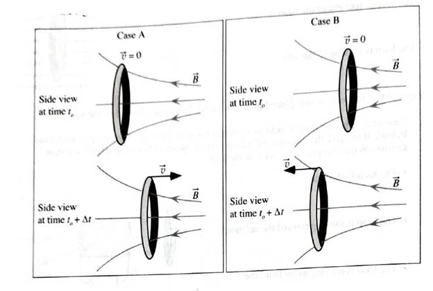
In each of the diagram below, the position of a loop is shown at two times,
The loop starts from rest in each case and is displaced to the right in Case A and to the left in Case B. On the diagrams indicate:
• the direction of the induced current through the wire of the loop,
• the magnetic moment of the loop,
• an area vector for each loop,
• the sign of the flux due to the external magnetic field (at both instants), and
• the sign of the induced flux (at both instants).
Want to see the full answer?
Check out a sample textbook solution
Chapter 8 Solutions
Tutorials in Introductory Physics
Additional Science Textbook Solutions
Lecture- Tutorials for Introductory Astronomy
Physics for Scientists and Engineers: A Strategic Approach with Modern Physics (4th Edition)
Applied Physics (11th Edition)
University Physics with Modern Physics (14th Edition)
Physics for Scientists and Engineers with Modern Physics
Essential University Physics: Volume 2 (3rd Edition)


- Use the worked example above to help you solve this problem. A coil with 21 turns of wire is wrapped on a frame with a square cross-section 2.14 cm on a side. Each turn has the same area, equal to that of the frame, and the total resistance of the coil is 0.561 Ω. An applied uniform magnetic field is perpendicular to the plane of the coil, as in the figure. (a) If the field changes uniformly from 0.00 T to 0.540 T in 0.731 s, find the induced emf in the coil while the field is changing. = (b) Find the magnitude of the induced current in the coil while the field is changing.I =arrow_forwardA square flat coil that has N turns, encloses an area A, and carries a current i has its central axis parallel to a uniform magnetic field in which it is immersed. What is the net torque on the coil? How would the torque change if you rotated the loop such that the field and its central axis are perpendicular? Make sure to answer both parts of the question and show all work.arrow_forwardA metal wire of mass m slides without friction on two horizontal rails spaced a distance d apart, as in the figure below. The track lies in a vertical uniform magnetic field . Generator G produces a constant current i in the wire and the rails (even as the wire moves). Find the velocity of the wire's motion as a function of time, assuming it to be stationary at t = 0. (Use any variable or symbol stated above along with the following as necessary: B for the magnitude of . All quantities are in SI units. Enter the sign of the expression, taking right to be positive.)arrow_forward
- Use the worked example above to help you solve this problem. A coil with 21 turns of wire is wrapped on a frame with a square cross-section 2.14 cm on a side. Each turn has the same area, equal to that of the frame, and the total resistance of the coil is 0.561 Ω. An applied uniform magnetic field is perpendicular to the plane of the coil, as in the figure. Suppose the magnetic field changes uniformly from 0.540 T to 0.162 T in the next 0.666 s. (a) Compute the induced emf in the coil. = V(b) Compute the induced current.I = A counterclockwise as viewed from above the coilarrow_forwardTwo colis are placed such that the longer coil (Coil #1) is placed inside of the shorter coil (Coil #2). The coils are both wound in the same direction (couterclockwise) and a current of 0.25 AA travels through the coils in the same direction. This situation is roughly illustrated in the figure below (although the number of turns, length, and radius in the image is NOT accurate or to scale) Coil #1 has 536 turns wrapped over a length of L1= 8.2cm and has a radius of 1.5cm . Coil #2 has 109 turns wrapped over a length of L2=2.0 cm and has a radius of 5.5 cm .arrow_forwardPlease answer if true or false, and why 1. If the motion of the magnet causes decreasing downward flux through the loop, The direction of the induced magnetic field would be against the downward flux. - True or False? 2. In a conducting rod moving in a uniform magnetic field, the magnetic field force supports the electric field force. - True or False? 3. The induced electric field is inversely proportional to the circumference of the loop, assuming all the other parameters are constant. - True or False?arrow_forward
- The arrangement illustrated in the figure below is composed of six finite straight wires of length l. The electric current flowing in such an arrangement is i. Using the Biot-Savart law, calculate: The magnitude of the magnetic field at point P due to the wire located along segment ab.The answer is in the second image. I am trying to use the standard biot-savart, which is B = (μ0*I/4π) * ∫dl * sinθ / r^2, and it always gives me 16*pi*l at the denominator, instead of 8pi*l. Solve it using B = (μ0*I/4π) * ∫dl * sinθ / r^2, and note that the image with the answer is correct.arrow_forwardthe figure below represents the xy plane that cuts perpendicularly two infinite and parallel wires that carry a current I, of the same magnitude, but in opposite directions.Draw the vectors to show the magnetic field B of each wire and resultant field Br at point P.NOTE: THE SECOND IMAGE IS THE ANSWER. I WOULD LIKE TO KNOW WHY Br = 2Bsin(θ) So, explain in details why Br = 2Bsinθ, there is no need to calculate anything elsearrow_forwardAlthough the net force produced by a magnetic field on a closed loop of a wire is zero, the loop has a net torque. A square loop of wire with sides of length 12 cm and carrying a current of 9A is placed inside a magnetic field with magnitude of 5T. What is the maximum magnitude of torque on the loop? Show your work.arrow_forward
- A circular loop of wire sits face on to 2 tesla magnetic field that points into the page, as shown in the upper diagram at right. The wire loop is turned a quarter turn by a crank, so that the right edge of the loop drops into the page and the left side of the loop comes out of the page. The radius of the loop is 20cm and the quarter turn takes 0.5 seconds. (a) What is the average emf induced in the loop, and does the current in the wire flow in the direction of the arrow on the loop or in the opposite direction? (b) If the crank continues to turn the loop another quarter turn in 0.5 seconds in the same direction, until it looks like the bottom picture, what will be the average emf induced in the wire, and does the current in the wire flow in the direction of the arrow or in the opposite direction?arrow_forwardFind the magnetic flux through all five surfaces of the wedge in Figure 1, if the magneticfield in the area is given by: B= (0.002î+ 0.003ĵ) Tand show that the total flux through the wedge is zero.In your answer, play particular attention to the neatness of the presentation and payattention to the following and apply them in your answer:(i) State the approach you are going to adopt to solve the problem.arrow_forwardThe current I in a long, straight wire is constant and is directed toward the right. Conducting loops A, B, C, and D are moving, in the directions shown, near the wire. a) Is the direction of the induced current clockwise or counterclockwise, or is the induced current zero for loop D? Briefly explain. b) What is the direction of the net force that the wire exerts on the loop D? (No explanation is needed.) c) Is the direction of the induced current clockwise or counterclockwise, or is the induced current zero for loop C? Briefly explain.arrow_forward
 Principles of Physics: A Calculus-Based TextPhysicsISBN:9781133104261Author:Raymond A. Serway, John W. JewettPublisher:Cengage Learning