
Concept explainers
Videos
Electric generator
Remove the battery and ammeter from circuit in part B and insert micro-ammeter as shown.
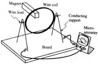
1. Suppose that the coil is made to spin by an external agent such as yourself.
Predict the deflection of the micro-ammeter needle throughout a complete revolution of the coil.
How would your prediction change if:
•the coil were made to rotate the other way?
•the poles of the magnet were reversed?
2. Check your predictions by gently rotating the coil so that it spins for a little time on its own before coming to a stop.
When the coil of the apparatus above is made to spin by an external agent, the apparatus is called an electric generator.

Learn your wayIncludes step-by-step video

Chapter 8 Solutions
Tutorials in Introductory Physics
Additional Science Textbook Solutions
Lecture- Tutorials for Introductory Astronomy
Cosmic Perspective Fundamentals
Conceptual Physical Science (6th Edition)
University Physics with Modern Physics (14th Edition)
Physics for Scientists and Engineers with Modern Physics
Physics for Scientists and Engineers: A Strategic Approach, Vol. 1 (Chs 1-21) (4th Edition)


- 1. What is the direction of the magnetic fields produced by the electromagnet? Is it from positive to negative terminal or from negative to positive terminal? 2. After disconnecting the switch (OFF), removing the battery and copper wire from the nail. Did the nail still attract the pins? (Explain) 3. If you increase the number of turns of the coil, Does the strength of the electromagnet increases?arrow_forwardFigure 3 shows a straight wire carrying a current in upwarddirection. The wire is placed near a wire loop. For each case described below, answer the following questions:a. What is the direction of the magnetic flux through theloop?b. Is the magnitude of the flux through the loop increasing ordecreasing with time?c. What is the direction of the magnetic field produced by theinduced current in the loop?d. What is the direction of the current induced in the loop?1. Case 1: The current is increasing.2. Case 2: The current is decreasing.3. Case 3: The current is constant but the loop is being pulledaway from the straight wire.arrow_forwardPlease just answer this question: Qualitatively discuss what effect considering the resistance of the conducting rails would have on your estimate of terminal velocity. Make sure to consider that as the rod slides,the overall resistance of the circuit increases as a function of that distance slid. Do you think this would lead to a larger or smaller terminal velocity than the one you calculated in part (b)? (Note if it helps: I calculated an induced current of 0.049A for part b).arrow_forward
- In the diagram above, a bar magnet is brought closer to a conducting wire loop with 7 Ω of resistance. As a result a uniform 3 A current is induced in the wire. What is the direction of the induced magnetic field at the center of the loop? Explain the reasoning behind your selection in detail.A) UpB) DownC) ClockwiseD) CounterclockwiseE) Cannot be determinedarrow_forwardI need a proper solution for this question ( well explained and understandable writing) After the switch is closed in the LC circuit shown in Figure , the charge on the capacitor is sometimes zero, but at such instants the current in the circuit is not zero. How is this behavior possible?arrow_forwardA 500-turn coil of area 0.00200 m^2 is rotated in a 2.00 T magnetic field. At what frequency, f, must the coil be rotated so that the generator produces a voltage amplitude of 250.0 V? Please also explain and show the steps you used to get there/the physics behind why/how you got to the answer to help me better understand. Thank you soo much. Also, the work and the explanation or most important because I already have the correct answer - I'm just unsure of how to get there.arrow_forward
- A rectangular loop of wire is pushed to the right, into a region containing a uniform magnetic field that points into the page, as shown below. (a) Which scenario below will have the greater induced voltage at any given moment? Briefly explain your reasoning. pushing the loop rapidly pushing the loop slowly Both will cause the same induced voltage in the loop. (b) Which scenario below will have the greatest induced voltage at any given moment? Briefly explain your reasoning. The width of the loop pushed into the region that contains the magnetic field is W = 1 m. • The width of the loop pushed into the region that contains the magnetic field is W = 2 m. • Both scenarios above will have the same induced voltage in the loop. (c) Which scenario below will have the greatest induced voltage? Briefly explain your reasoning. The moment that 25% of the loop is in the region containing the magnetic field (and 75% of the loop is not yet in the region containing the magnetic field).…arrow_forwardShown to the right is a long wire (you may assume the wire to be infinitely long). The wire carries a current i as shown, which produces a magnetic field around it (not shown). Also shown are five charges and their direction of motion (direction of ~v). Charge 5 is moving into the page. For the questions below, write your answer in terms of ”towards the top, bottom, left, right, into, or out of the page”. (a) Determine the direction of the magnetic field (from the wire) at the location of each of those charges. (b) Determine the direction of the magnetic force on each of those charges.arrow_forward1. What is the direction of the induced current when the North Pole is move away from the coil? Explain your answer 2. What is the direction of the induced current when the North Pole is is approaching the coil? Explain your answerarrow_forward
- The circular conducting loops shown in the accompanying figure are parallel, perpendicular to the plane of the page, and coaxial. (a) When the switch S isclosed, what is the direction of the current induced in D? (b) When the switch is opened, what is the direction of the current induced in loop D?arrow_forwardA single turn coil of radius 7.00 cm is held in a vertical plane and a magnet is rapidly moved relative to the coil as shown in the diagram below. The field inside the coil changes from 0.045 T to 0.020 T in a matter of 0.300 seconds. If the resistance of the coil is 5.00 Ohms, what is the magnitude and direction of the induced current in a coil as viewed from the side of the magnet? Make sure to include clear explanations for your choice of current direction.arrow_forwardNote: Elaborate and provide a screenshot of your observation including the corresponding equation (applicable to all questions) F. Lasty, try putting the magnet in the loops and click the magnet flip button. What happens as you spin the magnet several times? G. Look at the Voltage needle as you spin it multiple times. What type of current do you think it is producing? AC or DC?arrow_forward
 College PhysicsPhysicsISBN:9781305952300Author:Raymond A. Serway, Chris VuillePublisher:Cengage Learning
 University Physics (14th Edition)PhysicsISBN:9780133969290Author:Hugh D. Young, Roger A. FreedmanPublisher:PEARSON
 Introduction To Quantum MechanicsPhysicsISBN:9781107189638Author:Griffiths, David J., Schroeter, Darrell F.Publisher:Cambridge University Press
 Physics for Scientists and EngineersPhysicsISBN:9781337553278Author:Raymond A. Serway, John W. JewettPublisher:Cengage Learning
 Lecture- Tutorials for Introductory AstronomyPhysicsISBN:9780321820464Author:Edward E. Prather, Tim P. Slater, Jeff P. Adams, Gina BrissendenPublisher:Addison-Wesley
 College Physics: A Strategic Approach (4th Editio...PhysicsISBN:9780134609034Author:Randall D. Knight (Professor Emeritus), Brian Jones, Stuart FieldPublisher:PEARSON