
Concept explainers
Videos
Simple electric motor
Obtain the equipment illustrated at right assemble it as shown.
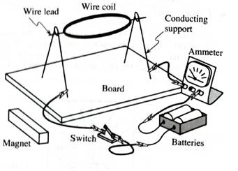
You should have:
•a magnet, a battery, a switch, some connecting, and an ammeter.
• a copper wire coil. The ends of the wire leads to the coil have been stripped of the insulating enamel coating so that half the wire is bare.
• twoconducting supports for the leads to the coil
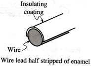
1. Examine the leads to the wire coil closely, so that you understand which portion of the wire has been stripped of the insulating coating.
For what orientations of the coil will there be a current through it due to the battery?
Check your answer by losing the switch and observing the deflection of the ammeter as you rotate the coil manually through one complete revolution.
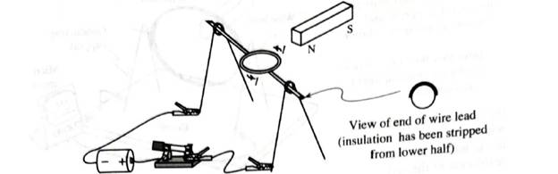
2. Hold one pole of the magnet near the coil. Close the switch. If the coil does not begin to spin, adjust the location of the magnet or gently rotate the coil to Stan it spinning.
Use the ideas that we have developed in this and previous tutorials to explain the motion of the wire coil. (The questions that follow may serve as a guide to help you develop an understanding of the operation of the motor.)
When the coil is in the position shown, there is a current, I, through it.
a. The coil is manually started spinning so that it rotates clockwise.
During which portions of the cycle does the coil from a complete circuit with the battery such that there is a current through the wire of the coil?
The current results in a magnetic moment that interacts with the magnetic field of the magnet. Will the interaction tend to increase or to decrease the angular speed of the coil? Explain.
b. The coil is manually started spinning so that it rotates counterclockwise:
During which portions of the cycle does the coil form a complete circuit with the battery so that there is a current through the wire of the coil?
The current results in a magnetic moment that interacts with the magnetic field of the magnet. Will the interaction tend to increase or to decrease the angular speed of the coil? Explain.
Check that the behavior of your motor is consistent with your answers.
4. Consider the following questions about the motor:
• Why was insulated wire used for the coil? Would bare wire also work? Explain.
• Would you expect the motor to work if the leads to the coil were stripped completely? Explain.
5. Predict the effect on the motor of (i) reversing the leads to the battery and (ii) reversing the orientation of the magnet
Check your predictions.
Want to see the full answer?
Check out a sample textbook solution
Chapter 8 Solutions
Tutorials in Introductory Physics
Additional Science Textbook Solutions
Conceptual Physical Science (6th Edition)
Conceptual Integrated Science
Cosmic Perspective Fundamentals
College Physics
University Physics (14th Edition)
College Physics: A Strategic Approach (3rd Edition)


- Shown to the right is a long wire (you may assume the wire to be infinitely long). The wire carries a current i as shown, which produces a magnetic field around it (not shown). Also shown are five charges and their direction of motion (direction of ~v). Charge 5 is moving into the page. For the questions below, write your answer in terms of ”towards the top, bottom, left, right, into, or out of the page”. (a) Determine the direction of the magnetic field (from the wire) at the location of each of those charges. (b) Determine the direction of the magnetic force on each of those charges.arrow_forwardThe aluminum ring hangs from a thin wire as shown in the attached picture below. Near the ring is the iron core of the electromagnet shown on the left side. Answer and justify: 1. Does current flow in the ring in the described situation, and if so, in which direction when the Electromagnet is switched on? 2. Is there current in the ring then, has the electromagnet been switched on for some time? In which direction does the current flow, if it does? 3. Does current flow in the ring when the current in the electromagnet is cut off? In which direction does the current flow, if it does?arrow_forwardTwo parallel wires carry currents as shown in the diagram to the right. What is the direction of the force acting on wire II? Explain the reasoning behind your selection in detail.A) leftB) rightC) out of the pageD) into the pageE) clockwisearrow_forward
- Note: Elaborate and provide a screenshot of your observation including the corresponding equation (applicable to all questions) F. Lasty, try putting the magnet in the loops and click the magnet flip button. What happens as you spin the magnet several times? G. Look at the Voltage needle as you spin it multiple times. What type of current do you think it is producing? AC or DC?arrow_forwardI need a proper solution for this question ( well explained and understandable writing) After the switch is closed in the LC circuit shown in Figure , the charge on the capacitor is sometimes zero, but at such instants the current in the circuit is not zero. How is this behavior possible?arrow_forwardI need a proper solution for this question ( understandable writing and well explained ) Will a transformer operate if a battery is used for the input voltage across the primary? Explainarrow_forward
- Please just answer this question: Qualitatively discuss what effect considering the resistance of the conducting rails would have on your estimate of terminal velocity. Make sure to consider that as the rod slides,the overall resistance of the circuit increases as a function of that distance slid. Do you think this would lead to a larger or smaller terminal velocity than the one you calculated in part (b)? (Note if it helps: I calculated an induced current of 0.049A for part b).arrow_forwardA rectangular loop of wire is placed midway between two long straight parallel conductors as shown in figure (11). The conductors carry currents i1 and i2 as indicated. If i1 is decreasing and i2 is constant, then the induced current in the loop is:arrow_forwardThe aluminum ring hangs from a thin wire as shown in the attached picture below. Near the ring is the iron core of the electromagnet shown on the left side. Answer and justify: a. Does current flow in the ring in the described situation, and if so, in which direction when the Electromagnet is switched on? b. Is there current in the ring then, has the electromagnet been switched on for some time? In which direction does the current flow, if it does? c. Does current flow in the ring when the current in the electromagnet is cut off? In which direction does the current flow, if it does? please label your answer as a b and carrow_forward
- Lab Procedure #1 – Induced Current vs. Velocity For this first lab procedure, you will only be changing the magnitude of the velocity. Keep the ‘Magnetic Field’, ‘Rail Separation’, and resistance under ‘Circuit Info’ at default and write their values down in Data Table 1 Data Table 1. B = L = R = what is B, L and R pls.arrow_forwardTwo straight wires carrying current are fixed at the locations shown in the figure below. Three field points (labeled A, B, and C) are also indicated in the figure. Sketch a vector diagram of magnetic fields produced at points A, B, and C in the corresponding boxes below. In each case, sketch the individual magnetic field vectors produced by each current, as well as the net magnetic field. Be sure to label your vectors clearly. (If one of the vectors is zero, explicitly say so.) Calculate the net magnetic field at point C. Express your answer in vector form.arrow_forwardThe problem below explores the basic principles behind electric generators, which we will discuss in class in detail. A 505 turn circular loop coil with a diameter of 3.9cm is initially held perpendicular to the Earth's magnetic field. The coil is then rotated in 7.6ms by 90 degrees, so the plane of the coil is parallel to the magnetic field. The average emf induced in the coil is 7.2V. Find the value of the Earth's magnetic field (in T) inducing the current in the coil.As an approximation, assume that the magnetic flux in the coil changes at a constant rate between its maximum and minimum values. Note that (see the previous problem) the flux through the coil is 505 times larger than if it was made out of one wire loop.arrow_forward
 College PhysicsPhysicsISBN:9781305952300Author:Raymond A. Serway, Chris VuillePublisher:Cengage Learning
 University Physics (14th Edition)PhysicsISBN:9780133969290Author:Hugh D. Young, Roger A. FreedmanPublisher:PEARSON
 Introduction To Quantum MechanicsPhysicsISBN:9781107189638Author:Griffiths, David J., Schroeter, Darrell F.Publisher:Cambridge University Press
 Physics for Scientists and EngineersPhysicsISBN:9781337553278Author:Raymond A. Serway, John W. JewettPublisher:Cengage Learning
 Lecture- Tutorials for Introductory AstronomyPhysicsISBN:9780321820464Author:Edward E. Prather, Tim P. Slater, Jeff P. Adams, Gina BrissendenPublisher:Addison-Wesley
 College Physics: A Strategic Approach (4th Editio...PhysicsISBN:9780134609034Author:Randall D. Knight (Professor Emeritus), Brian Jones, Stuart FieldPublisher:PEARSON