
MECHANICS OF MATERIALS
10th Edition
ISBN: 2818440034374
Author: HIBBELER
Publisher: PEARSON
expand_more
expand_more
format_list_bulleted
Videos
Textbook Question
Chapter 8.1, Problem 8.15P
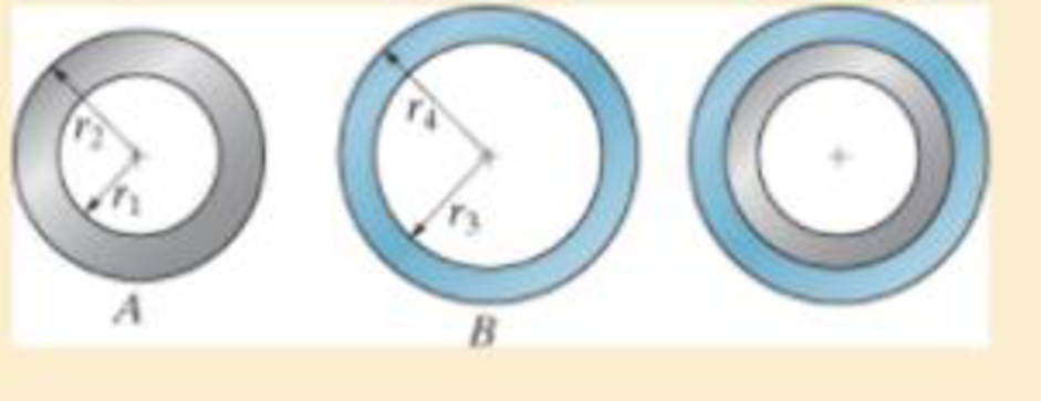
The inner ring A has an inner radius r1 and outer radius r2. The outer ring B has an inner radius r3 and an outer radius r4, and r2 > r3. If the outer ring is heated and then fitted over the inner ring, determine the pressure between the two rings when ring B reaches the temperature of the inner ring. The material has a modulus of elasticity of E and a coefficient of thermal expansion of α
 .
.
Expert Solution & Answer
Want to see the full answer?
Check out a sample textbook solution
Students have asked these similar questions
The inner ring A has an inner radius r1 and outer radius r2. The outer ring B has an inner radius r3 and an outer radius r4, and r2 7 r3. If the outer ring is heated and then fitted over the inner ring, determine the pressure between the two rings when ring B reaches the temperature of the inner ring. The material has a modulus of elasticity of E and a coefficient of thermal expansion of a.
The center rod CD of the assembly is heated from T₁ = 30 °C to T₂ = 165
°C using electrical resistance heating. At the lower temperature T₁ the gap
between C and the rigid bar is 0.7 mm. Rods AB and EF are made of
steel, and each has a cross-sectional area of 125 mm². CD is made of
aluminum and has a cross-sectional area of 375 mm². Est = 200 GPa,
Eal = 70 GPa, and cal = 23 (10-) /°C.
(Figure 1)
Figure
0.7 mm
240 mm
300 mm
Determine the force in the rod AB caused by the increase in temperature.
Express your answer to three significant figures and include the appropriate units.
FAB =
Submit
Part B
FEF=
_O
Submit
μA
Value
Request Answer
Determine the force in the rod EF caused by the increase in temperature.
Express your answer to three significant figures and include the appropriate units.
|μA
Value
Units
Request Answer
?
Units
?
The bar has a cross-sectional area A, length L, modulus of elasticity E, and coefficient of thermal expansion a. The temperature of the bar changes uniformly along its length from TA at A to TB at B so that at any point x alongthe bar T = TA + x(TB - TA)>L. Determine the force the bar exerts on the rigid walls. Initially, no axial force is in the bar and the bar has a temperature of TA.
Chapter 8 Solutions
MECHANICS OF MATERIALS
Ch. 8.1 - If it is subjected to an internal pressure of p =...Ch. 8.1 - If it is subjected to an internal pressure of p =...Ch. 8.1 - The thin-walled cylinder can be supported in one...Ch. 8.1 - If the inner diameter of the tank is 22 in., and...Ch. 8.1 - Air pressure in the cylinder is increased by...Ch. 8.1 - Determine the maximum force P that can be exerted...Ch. 8.1 - A boiler is constructed of 8-mm-thick steel plates...Ch. 8.1 - 88. The steel water pipe has an inner diameter of...Ch. 8.1 - The steel water pipe has an inner diameter of 12...Ch. 8.1 - The A-36-steel band is 2 in. wide and is secured...
Ch. 8.1 - The gas pipe line is supported every 20 ft by...Ch. 8.1 - A pressure-vessel head is fabricated by welding...Ch. 8.1 - An A-36-steel hoop has an inner diameter of 23.99...Ch. 8.1 - The ring, having the dimensions shown, is placed...Ch. 8.1 - The inner ring A has an inner radius r1 and outer...Ch. 8.1 - Two hemispheres having an inner radius of 2 ft and...Ch. 8.1 - In order to increase the strength of the pressure...Ch. 8.2 - Show the results on the left segment.Ch. 8.2 - Show the stress that each of these loads produce...Ch. 8.2 - Fundamental Problems F81. Determine the normal...Ch. 8.2 - Show the results in a differential element at the...Ch. 8.2 - Determine the state of stress at point A on the...Ch. 8.2 - Determine the magnitude of the load P that will...Ch. 8.2 - Determine the state of stress at point B. Show the...Ch. 8.2 - Determine the state of stress at point A on the...Ch. 8.2 - Determine the state of stress at point A on the...Ch. 8.2 - Show the results in a differential element at the...Ch. 8.2 - Determine the shortest distance d to the edge of...Ch. 8.2 - The plate has a thickness of 20 mm and P acts...Ch. 8.2 - Plot the distribution of normal stress acting...Ch. 8.2 - Also, plot the normal-stress distribution over the...Ch. 8.2 - If the allowable normal stress for the steel is...Ch. 8.2 - If the applied force P = 1.50 kip, determine the...Ch. 8.2 - Determine the maximum normal stress on the cross...Ch. 8.2 - If the wood has an allowable normal stress of...Ch. 8.2 - Determine the maximum normal stress along section...Ch. 8.2 - Sketch the stress distribution along section aa of...Ch. 8.2 - Sketch the normal-stress distribution acting over...Ch. 8.2 - Determine the state of stress at points A and B,...Ch. 8.2 - If the force of 100 N is applied to the handles,...Ch. 8.2 - Determine the stress components at point A on the...Ch. 8.2 - Determine the stress components at point B on the...Ch. 8.2 - Determine the normal stress developed at points A...Ch. 8.2 - Sketch the normal-stress distribution acting over...Ch. 8.2 - Determine the state of stress at points A and B,...Ch. 8.2 - Determine the state of stress at point A on the...Ch. 8.2 - Determine the state of stress at point B on the...Ch. 8.2 - Determine the state of stress acting at point D....Ch. 8.2 - Determine the state of stress acting at point E....Ch. 8.2 - If it is subjected to the force system shown,...Ch. 8.2 - Solve Prob.840 for point B.Ch. 8.2 - Determine the stress components acting on the...Ch. 8.2 - Determine the stress components acting on the...Ch. 8.2 - Neglect the weight of the block.Ch. 8.2 - Neglect the weight of the block.Ch. 8.2 - He is supported uniformly by two bars, each having...Ch. 8.2 - Determine the state of stress at point A, and show...Ch. 8.2 - Determine the state of stress at point B, and show...Ch. 8.2 - Determine the state of stress at point C, and show...Ch. 8.2 - Determine the maximum radius e at which the load P...Ch. 8.2 - Specify the region to which this load can be...Ch. 8.2 - Determine the smallest force P that can be applied...Ch. 8.2 - The coiled spring is subjected to a force P. If we...Ch. 8.2 - The pins at C and D are at the same location as...Ch. 8.2 - Determine the state of stress at point A, and show...Ch. 8.2 - Determine the state of stress at point B, and show...Ch. 8.2 - Determine the stress components at points A and B...Ch. 8.2 - Determine the stress components at points C and D...Ch. 8.2 - Determine the stress components in the support...Ch. 8.2 - Determine the stress components in the support...Ch. 8.2 - If the force at the ram on the clamp at D is P= 8...Ch. 8.2 - Determine the maximum ram force P that can be...Ch. 8.2 - and an outer radius of 3.00 in. If the face of the...Ch. 8.2 - for points E and F.Ch. 8.2 - Determine the stress components at points A and B...Ch. 8.2 - Solve Prob.8-65 for points C and D.Ch. 8.2 - Due to internal gearing, this causes the block to...Ch. 8.2 - Determine the state of stress at point A and show...Ch. 8.2 - Solve Prob.868 for point B.Ch. 8.2 - Determine the stress components at point A. Sketch...Ch. 8.2 - for the stress components at point B.Ch. 8.2 - Determine the state of stress at point A at...Ch. 8.2 - Determine the state of stress at point B at...Ch. 8 - If it supports a cable loading of 800 lb,...Ch. 8 - Determine the state of stress at point E on the...Ch. 8 - Determine the state of stress at point F on the...Ch. 8 - The suspender arm AE has a square cross-sectional...Ch. 8 - If the cross section of the femur at section aa...Ch. 8 - If it has a mass of 5 kg/m, determine the largest...Ch. 8 - and is used to support the vertical reactions of...Ch. 8 - and is used to support the vertical reactions of...
Knowledge Booster


Learn more about
Need a deep-dive on the concept behind this application? Look no further. Learn more about this topic, mechanical-engineering and related others by exploring similar questions and additional content below.Similar questions
- The central bar CD of the assembly is heated from 30 ° C to 180 ° C by means of an electrical resistance. Also the two bars AB and EF are heated from 30 ° C to 50 ° C. At the lower temperature of 30 ° C, the space between C and the rigid bar is 0.7 mm. Determine the force in bars AB and EF caused by the increase in temperature. Bars AB and EF are made of steel and each has a cross-sectional area of 125 mm ^ 2; CD is aluminum with a cross-sectional area of 375 mm ^ 2. Steel = 200GP; Ealuminum = 70 GPa; alpha steel = 12 X10 ^ -6 (1 / ºC); alpha aluminum = 23 X10 ^ -6 (1 / ° C).arrow_forward2. The bar has a cross-sectional area A, length L, modulus of elasticity E, and coefficient of thermal expansion a. The temperature of the bar changes uniformly along its length from TA at A to TB at B so that at any point x along the bar T = TA + x(TB – TA)/L. Determine the force the bar exerts on the rigid walls. Initially no axial force is in the bar and the bar has a temperature of TA. A B TA TBarrow_forwardThe wires AB and AC are made of steel, and wire AD is made of copper. Before the 150-lb force is applied, AB and AC are each 60 in. long and AD is 40 in. long. If the temperature is increased by 80 F, determine the force in each wire needed to support the load. Each wire has a cross-sectionalarea of 0.0123 in2. Take Est = 29(10 3) ksi, Ecu = 17(10 3) ksi, fast = 8(10 6)> F, acu = 9.60(10 -6)> F.arrow_forward
- The cylinder CD of the assembly is heated from T1 = 30°C to T2 = 180°C using electrical resistance. Also, the two end rods AB and EF are heated from T1 = 30°C to T2 = 50°C. At the lower temperature T1 the gap between C and the rigid bar is 0.7 mm. Determine the force in rods AB and EF caused by the increase in temperature. Rods AB and EF are made of steel, and each has a cross-sectional area of 125 mm2. CD is made of aluminum and has a cross-sectional area of 375 mm2. Est = 200 GPa, Eal = 70 GPa, ast = 12(10-6)>°C, and aal = 23(10-6)>°C.arrow_forward3) The plug has a diameter of 30 mm and fits with a rigid sleeve having an inner diameter of 32 mm. Both the plug and the sleeve are 50 mm long. Determine the axial pressure P that must be applied to the top of the plug to cause it to contact the sides of the sleeve. Also, how far must the plug be compressed downward to do this? The plug is made from a material for which E = 5 MPa, v = 0.45. Parrow_forwardThe wires AB and AC are made of steel, and wire AD is made of aluminum. Before the 300 kN force is applied, AB and AC are each 150 mm. long and AD is 100 mm. long. If the temperature is increased by 30°C, determine the force in each wire needed to support the load. Take Est = 200 GPa, Eal = 70 GPa, st = 12 (10") / °C, aal = 23 (10") / °C. Each wire has a cross-sectional area of 0.02 mm². B 100 mm 45° 45° 150 mm 150 mm A 300 kNarrow_forward
- 3. The rigid bar ABC and EFG are supported by pins at A and G. The vertical rods are made of steel (rod DC and rod BE). Determine the vertical displacement at C if the change in temperature is 50°C. Use a = 0.0000117/°C and E = 200 GPa. Neglect the weight of the members. A=125 sq. mm L= 2 m A 2 m B 2 m A=135 sq. mm L = 3 m E G 2 m F 3 m 50 kNarrow_forwardThe cylinder CD of the assembly is heated from T1 = 30°C to T2 = 180°C using electrical resistance. At the lower temperature T1 the gap between C and the rigid bar is 0.7 mm. Determine the force in rods AB and EF caused bythe increase in temperature. Rods AB and EF are made of steel, and each has a cross-sectional area of 125 mm2. CD is made of aluminum and has a cross-sectional area of 375 mm2. Est = 200 GPa, Eal = 70 GPa, and aal = 23(10-6)>°C.arrow_forwardAn A-36-steel hoop has an inner diameter of 23.99 in., a thickness of 0.25 in., and a width of 1 in. If it and the 24-in.-diameter A rigid cylinder has a temperature of 65° F, determine the temperature to which the hoop should be heated in order for it to just slip over the cylinder. What is the pressure the hoop exerts on the cylinder, and the tensile stress in the ring when it cools back down to 65° F?arrow_forward
- The stepped rod shown in the figure is made of Al 2014-T6 aluminum alloy. At temperature T1 = 20°C, there is a gap of 0.2 mm between point A and the rigid wall. If the temperature is increased to T2-50°C and an axial compressive force of P= 20 kN is applied at point B, determine the support reactions at points A and C. 80 mm B C A 20 kN 120 mm 400 mm 600 mm 0,2 mmarrow_forwardTwo cylindrical rods, one of steel and the other brass are joined at C and restrained by rigid support at A, At the support E in a room temperature of 20°C a gap of 0.5mm exist. The system is loaded with F1= (67 and F2 S 16 as shown. Determine when the environmental temperature will reach to 240°C, (a) the reactions at A and E. and (b) the change in length of steel. Brass Steel E=105GPA E=200GPA a=21.6x10⁶/°C a=17.3x10/°C Dimensions in mm 150 120 0.5 300 200. A C D E Brass B. Steel F1(kN) F2(kN) 80-mm diam. 40-mm diam.arrow_forwardThe 58-mm-diameter cylinder is made from Am 1004-T61 magnesium and is placed the clamp when the temperature is T₁ = 20°C. (Figure 1) Figure 100 mm 150 mm Part A If the 304-stainless-steel carriage bolts of the clamp each have a diameter of 9 mm, and they hold the cylinder snug with negligible force against the rigid jaws, determine the force in the cylinder when the temperature rises to T₂ = 130°C. Express your answer to three significant figures and include the appropriate units. F = 2.37 Submit μÀ ^ Provide Feedback KN WX Previous Answers Request Answer ? X Incorrect; Try Again; 3 attempts remaining Next >arrow_forward
arrow_back_ios
SEE MORE QUESTIONS
arrow_forward_ios
Recommended textbooks for you
 Elements Of ElectromagneticsMechanical EngineeringISBN:9780190698614Author:Sadiku, Matthew N. O.Publisher:Oxford University Press
 Mechanics of Materials (10th Edition)Mechanical EngineeringISBN:9780134319650Author:Russell C. HibbelerPublisher:PEARSON
 Thermodynamics: An Engineering ApproachMechanical EngineeringISBN:9781259822674Author:Yunus A. Cengel Dr., Michael A. BolesPublisher:McGraw-Hill Education
 Control Systems EngineeringMechanical EngineeringISBN:9781118170519Author:Norman S. NisePublisher:WILEY
 Mechanics of Materials (MindTap Course List)Mechanical EngineeringISBN:9781337093347Author:Barry J. Goodno, James M. GerePublisher:Cengage Learning
 Engineering Mechanics: StaticsMechanical EngineeringISBN:9781118807330Author:James L. Meriam, L. G. Kraige, J. N. BoltonPublisher:WILEY
Elements Of Electromagnetics
Mechanical Engineering
ISBN:9780190698614
Author:Sadiku, Matthew N. O.
Publisher:Oxford University Press
Mechanics of Materials (10th Edition)
Mechanical Engineering
ISBN:9780134319650
Author:Russell C. Hibbeler
Publisher:PEARSON
Thermodynamics: An Engineering Approach
Mechanical Engineering
ISBN:9781259822674
Author:Yunus A. Cengel Dr., Michael A. Boles
Publisher:McGraw-Hill Education
Control Systems Engineering
Mechanical Engineering
ISBN:9781118170519
Author:Norman S. Nise
Publisher:WILEY
Mechanics of Materials (MindTap Course List)
Mechanical Engineering
ISBN:9781337093347
Author:Barry J. Goodno, James M. Gere
Publisher:Cengage Learning
Engineering Mechanics: Statics
Mechanical Engineering
ISBN:9781118807330
Author:James L. Meriam, L. G. Kraige, J. N. Bolton
Publisher:WILEY
Material Properties 101; Author: Real Engineering;https://www.youtube.com/watch?v=BHZALtqAjeM;License: Standard YouTube License, CC-BY
Mechanical Properties of Materials; Author: Academic Gain Tutorials;https://www.youtube.com/watch?v=6L-r3hx0NLM;License: Standard Youtube License