
MECHANICS OF MATERIALS
10th Edition
ISBN: 2818440034374
Author: HIBBELER
Publisher: PEARSON
expand_more
expand_more
format_list_bulleted
Concept explainers
Videos
Textbook Question
Chapter 8.2, Problem 8.27P
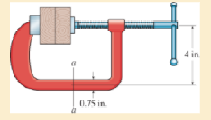
Sketch the stress distribution along section a–a of the clamp. The cross section is rectangular, 0.75 in. by 0.50 in.
Expert Solution & Answer
Want to see the full answer?
Check out a sample textbook solution
Students have asked these similar questions
X
A purse hook is used to hang a handbag from the edge of a table with L = 50 mm. If the cross section at a-a
has a diameter of d = 3 mm and the hook is supporting a purse with a mass of 3 kg, determine the normal
stress profile. For what value of y (using the coordinates pictured for section a-a) with the normal stress be
zero. If it is never zero enter "nde" for "not defined".
N
-L→
a.
a
AB
C
Follow sign convention that tension is positive and compression is negative.
Normal stress at point A, σA=
MPa
Normal stress at point B, σB =
MPa
Normal stress at point C, σc =
MPa
y position where normal stress equals zero =
mm
Section a-a
d
The book is subjected to the force of 60 lb Determine the state of stress
at point A at section a-a. The cross section is circular and has a
diameter of 0.5 in. Use the curved-beam formula to compute the bending
stress
(Figure 1)
Figure
1.5 in.
13
45°
B
1 of 1 >
▾ Part A
Determine the normal stress.
Express your answer using three significant figures and include the appropriate units. Enter negative value in the case of compression and positive value in the case
of tension.
g=
Value
Submit
Part B
←
A
psi
Previous Answers Request Answer
X Incorrect; Try Again; 4 attempts remaining
✓ Correct
< Return to Assignment
Ċ 129 ?
Determine the shear stress
Express your answer using three significant figures and include the appropriate units.
T= 0 psi
Previous Answers
Provide Feedback
Determine the state of stress at point q. The pipe has an inner diameter of D₁ = 1.0 in and an outer diameter of
= 1.8 in. Use the exact expression for Q, if needed. Label the reultant forces on the cross section below. Report
your answer (3x3 matrix) in psi to one decimal place.
Do
4 in.
Y
4 in.
150 lb
6 in.
50 lb
10 in.
200 lb
150 lb
X
N
Y
Chapter 8 Solutions
MECHANICS OF MATERIALS
Ch. 8.1 - If it is subjected to an internal pressure of p =...Ch. 8.1 - If it is subjected to an internal pressure of p =...Ch. 8.1 - The thin-walled cylinder can be supported in one...Ch. 8.1 - If the inner diameter of the tank is 22 in., and...Ch. 8.1 - Air pressure in the cylinder is increased by...Ch. 8.1 - Determine the maximum force P that can be exerted...Ch. 8.1 - A boiler is constructed of 8-mm-thick steel plates...Ch. 8.1 - 88. The steel water pipe has an inner diameter of...Ch. 8.1 - The steel water pipe has an inner diameter of 12...Ch. 8.1 - The A-36-steel band is 2 in. wide and is secured...
Ch. 8.1 - The gas pipe line is supported every 20 ft by...Ch. 8.1 - A pressure-vessel head is fabricated by welding...Ch. 8.1 - An A-36-steel hoop has an inner diameter of 23.99...Ch. 8.1 - The ring, having the dimensions shown, is placed...Ch. 8.1 - The inner ring A has an inner radius r1 and outer...Ch. 8.1 - Two hemispheres having an inner radius of 2 ft and...Ch. 8.1 - In order to increase the strength of the pressure...Ch. 8.2 - Show the results on the left segment.Ch. 8.2 - Show the stress that each of these loads produce...Ch. 8.2 - Fundamental Problems F81. Determine the normal...Ch. 8.2 - Show the results in a differential element at the...Ch. 8.2 - Determine the state of stress at point A on the...Ch. 8.2 - Determine the magnitude of the load P that will...Ch. 8.2 - Determine the state of stress at point B. Show the...Ch. 8.2 - Determine the state of stress at point A on the...Ch. 8.2 - Determine the state of stress at point A on the...Ch. 8.2 - Show the results in a differential element at the...Ch. 8.2 - Determine the shortest distance d to the edge of...Ch. 8.2 - The plate has a thickness of 20 mm and P acts...Ch. 8.2 - Plot the distribution of normal stress acting...Ch. 8.2 - Also, plot the normal-stress distribution over the...Ch. 8.2 - If the allowable normal stress for the steel is...Ch. 8.2 - If the applied force P = 1.50 kip, determine the...Ch. 8.2 - Determine the maximum normal stress on the cross...Ch. 8.2 - If the wood has an allowable normal stress of...Ch. 8.2 - Determine the maximum normal stress along section...Ch. 8.2 - Sketch the stress distribution along section aa of...Ch. 8.2 - Sketch the normal-stress distribution acting over...Ch. 8.2 - Determine the state of stress at points A and B,...Ch. 8.2 - If the force of 100 N is applied to the handles,...Ch. 8.2 - Determine the stress components at point A on the...Ch. 8.2 - Determine the stress components at point B on the...Ch. 8.2 - Determine the normal stress developed at points A...Ch. 8.2 - Sketch the normal-stress distribution acting over...Ch. 8.2 - Determine the state of stress at points A and B,...Ch. 8.2 - Determine the state of stress at point A on the...Ch. 8.2 - Determine the state of stress at point B on the...Ch. 8.2 - Determine the state of stress acting at point D....Ch. 8.2 - Determine the state of stress acting at point E....Ch. 8.2 - If it is subjected to the force system shown,...Ch. 8.2 - Solve Prob.840 for point B.Ch. 8.2 - Determine the stress components acting on the...Ch. 8.2 - Determine the stress components acting on the...Ch. 8.2 - Neglect the weight of the block.Ch. 8.2 - Neglect the weight of the block.Ch. 8.2 - He is supported uniformly by two bars, each having...Ch. 8.2 - Determine the state of stress at point A, and show...Ch. 8.2 - Determine the state of stress at point B, and show...Ch. 8.2 - Determine the state of stress at point C, and show...Ch. 8.2 - Determine the maximum radius e at which the load P...Ch. 8.2 - Specify the region to which this load can be...Ch. 8.2 - Determine the smallest force P that can be applied...Ch. 8.2 - The coiled spring is subjected to a force P. If we...Ch. 8.2 - The pins at C and D are at the same location as...Ch. 8.2 - Determine the state of stress at point A, and show...Ch. 8.2 - Determine the state of stress at point B, and show...Ch. 8.2 - Determine the stress components at points A and B...Ch. 8.2 - Determine the stress components at points C and D...Ch. 8.2 - Determine the stress components in the support...Ch. 8.2 - Determine the stress components in the support...Ch. 8.2 - If the force at the ram on the clamp at D is P= 8...Ch. 8.2 - Determine the maximum ram force P that can be...Ch. 8.2 - and an outer radius of 3.00 in. If the face of the...Ch. 8.2 - for points E and F.Ch. 8.2 - Determine the stress components at points A and B...Ch. 8.2 - Solve Prob.8-65 for points C and D.Ch. 8.2 - Due to internal gearing, this causes the block to...Ch. 8.2 - Determine the state of stress at point A and show...Ch. 8.2 - Solve Prob.868 for point B.Ch. 8.2 - Determine the stress components at point A. Sketch...Ch. 8.2 - for the stress components at point B.Ch. 8.2 - Determine the state of stress at point A at...Ch. 8.2 - Determine the state of stress at point B at...Ch. 8 - If it supports a cable loading of 800 lb,...Ch. 8 - Determine the state of stress at point E on the...Ch. 8 - Determine the state of stress at point F on the...Ch. 8 - The suspender arm AE has a square cross-sectional...Ch. 8 - If the cross section of the femur at section aa...Ch. 8 - If it has a mass of 5 kg/m, determine the largest...Ch. 8 - and is used to support the vertical reactions of...Ch. 8 - and is used to support the vertical reactions of...
Knowledge Booster


Learn more about
Need a deep-dive on the concept behind this application? Look no further. Learn more about this topic, mechanical-engineering and related others by exploring similar questions and additional content below.Similar questions
- The shear stress is maximum on the principal plane Select one: O True O Falsearrow_forwardDetermine the average normal stress on the cross section. Sketch the normal stress distribution over the cross section.arrow_forwardDetermine the normal stress in each section of the assembly. The diameter of the solid shaft of each section is 0.50 inches. Give the answer in Ib/in?. Assume Point A is a fixed support and the block at A is rigid. Indicate if it is in tension or compression. 3.50 kip 1.75 kip 5.00 kip B 3.50 kip A 1.75 kip 18 in. 12 in.- 16 in: CAR = units %3D IIarrow_forward
- The screw of the clamp exerts a compressive force of 500 lb on the wood blocks. Determine the maximum normal stress along section a–a. The cross section is rectangular, 0.75 in. by 0.50 in.arrow_forward6kN and 1.0KNM loads are applied to the top of the 62-mm-diameter cast-iron as shown. Determine the principal stresses (max and min normal stresses), principal planes (orientation of plane for max-min normal stresses) and max shear stress by using Mohr's circle. Hint: Use given coordinate system. So, H is on x-z plane and K is on y- z plane 1.0 kN.m 6 kN X 220 mmarrow_forwardThe eye hook has the dimensions shown. If it supports a cable loading of 800 lb, determine the maximum normal stress at section a–a and sketch the stress distribution acting over the cross section. Use the curved-beam formula to calculate the bending stress.arrow_forward
- The vertical links (at BD and CE) have a thickness = 5.4 and width = 31.2 mm uniform rectangular cross section. Determine the maximum value of the average normal stress in the links connecting (a) points B and D, (b) points C and E and choose the correct options. Applied load is 18.9 N, diameter of the pin is half of the width. All the options have been rounded off to two decimal places. 0.4 m 0.25 m 0.2 m O a. The stress in member BD is =0.18 MPa O b. The stress in member BD is =0.09 MPa O c. The stress in member BD is =-0.07 MPa O d. The stress in member BD is =-0.14 MPa O e. The stress in member CE is =-0.04 MPa O f. The stress in member CE is =-0.07 MPa O g. The stress in member CE is =-0.18 MPa O h. The stress in member CE is =-0.18 MPaarrow_forwardGiven the section is subjected to a moment of 500 N-m, calculate the normal stress in MPa at the bottom of the section. Use positive for tension and negative for compression. 10 mm 30 mm 10 mm 30 mmarrow_forwardThe joint is subjected to the axial member force of 6 kips. Determine the average normal stress acting on sections AB and BC. Assume the member is smooth and is 1.5 in thick. Tip: You can determine the forces by making a FBD in a concurrent point.arrow_forward
- 1. The pictured link acts as a part of the elevator control for a small airplane. If the attached aluminum tube has an inner diameter of 25 mm and a wall thickness of 5 mm, determine the shear stress in the outer and inner surfaces of the tube when a cable force of 600 N is applied to the cables. Also, sketch the shear-stress distribution over the cross-section.arrow_forwardThe joint is subjected to the axial member force of 6 kips. Determine the average normal stress acting on sections AB and BC. Assume the member is smooth and is 1.5 in thick. . Tip: You can determine the forces by making a FBD in a concurrent point. 1.5 in B 20⁰ 4.5 in. 6 kip 50⁰arrow_forwardSomeone already solved this and the answr is .0212 and -0.025. My question is is it okay to solve this even if it is not in equilibrium? Why?arrow_forward
arrow_back_ios
SEE MORE QUESTIONS
arrow_forward_ios
Recommended textbooks for you
 Elements Of ElectromagneticsMechanical EngineeringISBN:9780190698614Author:Sadiku, Matthew N. O.Publisher:Oxford University Press
 Mechanics of Materials (10th Edition)Mechanical EngineeringISBN:9780134319650Author:Russell C. HibbelerPublisher:PEARSON
 Thermodynamics: An Engineering ApproachMechanical EngineeringISBN:9781259822674Author:Yunus A. Cengel Dr., Michael A. BolesPublisher:McGraw-Hill Education
 Control Systems EngineeringMechanical EngineeringISBN:9781118170519Author:Norman S. NisePublisher:WILEY
 Mechanics of Materials (MindTap Course List)Mechanical EngineeringISBN:9781337093347Author:Barry J. Goodno, James M. GerePublisher:Cengage Learning
 Engineering Mechanics: StaticsMechanical EngineeringISBN:9781118807330Author:James L. Meriam, L. G. Kraige, J. N. BoltonPublisher:WILEY
Elements Of Electromagnetics
Mechanical Engineering
ISBN:9780190698614
Author:Sadiku, Matthew N. O.
Publisher:Oxford University Press
Mechanics of Materials (10th Edition)
Mechanical Engineering
ISBN:9780134319650
Author:Russell C. Hibbeler
Publisher:PEARSON
Thermodynamics: An Engineering Approach
Mechanical Engineering
ISBN:9781259822674
Author:Yunus A. Cengel Dr., Michael A. Boles
Publisher:McGraw-Hill Education
Control Systems Engineering
Mechanical Engineering
ISBN:9781118170519
Author:Norman S. Nise
Publisher:WILEY
Mechanics of Materials (MindTap Course List)
Mechanical Engineering
ISBN:9781337093347
Author:Barry J. Goodno, James M. Gere
Publisher:Cengage Learning
Engineering Mechanics: Statics
Mechanical Engineering
ISBN:9781118807330
Author:James L. Meriam, L. G. Kraige, J. N. Bolton
Publisher:WILEY
Everything About COMBINED LOADING in 10 Minutes! Mechanics of Materials; Author: Less Boring Lectures;https://www.youtube.com/watch?v=N-PlI900hSg;License: Standard youtube license