
Concept explainers
Videos
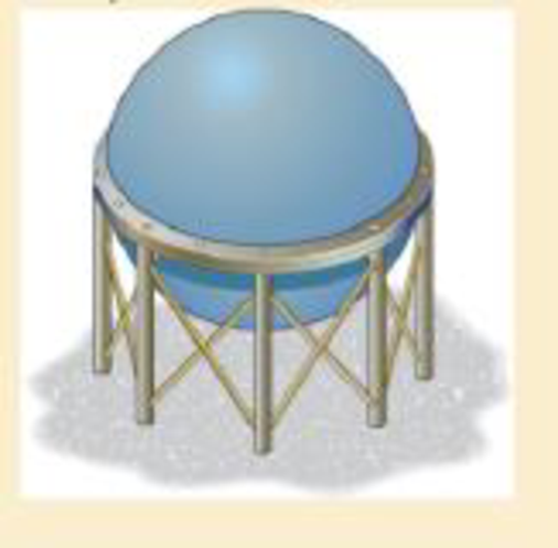
Two hemispheres having an inner radius of 2 ft and wall thickness of 0.25 in. are fitted together, and the inside pressure is reduced to − 10 psi. If the coefficient of static friction is μs = 0.5 between the hemispheres, determine (a) the torque T needed to initiate the rotation of the top hemisphere relative to the bottom one, (b) the vertical force needed to pull the top hemisphere of the bottom one, and (c) the horizontal force needed to slide the top hemisphere off the bottom one.
Want to see the full answer?
Check out a sample textbook solution
Chapter 8 Solutions
MECHANICS OF MATERIALS
Additional Engineering Textbook Solutions
Mechanics of Materials, 7th Edition
Thermodynamics: An Engineering Approach
Vector Mechanics for Engineers: Statics, 11th Edition
Foundations of Materials Science and Engineering
Vector Mechanics for Engineers: Dynamics
Vector Mechanics for Engineers: Statics


- The single-plate clutch transmits the torque C from the input shaft on the left to the output shaft on the right. Compression springs between the clutch housing and the pressure plate provide the necessary pressure on the friction surface. The splines prevent the clutch plate from rotating relative to the output shaft. If Ri=4 in. and R0=9 in., determine the total force that must be applied to the pressure plate by the springs if the clutch is to transmit a torque of C=56lbft when it is new.arrow_forwardThe screw of the clamp has a square thread of pitch 0.16 in. and a mean diameter of 0.6 in. The coefficient of static friction between the threads is 0.4. Determine (a) the torque C0 that must be applied to the screw in order to produce a 28-lb clamping force at A; and (b) the torque required to loosen the clamp.arrow_forwardThe square-threaded screw 0f the C-clamp has a mean diameter of 8 mm and a pitch of 1.6 mm. The coefficient of static friction between the threads is 0.2. If the torque C=1.50Nm is used to tighten the clamp, determine (a) the clamping force; and (b) the torque required to loosen the clamp.arrow_forward
- The frictional coefficient has a value of 0.26795, and the normal force is 20kN. Determine the angle of friction.arrow_forwardThe 81-lb force Pis applied to the 190-lb crate, which is stationary before the force is applied. Determine the magnitude and direction of the friction force Fexerted by the horizontal surface on the crate. The friction force is positive if to the right, negative if to the left. Assume 4, = 0.41, Hx = 0.33. Answer: F= i 77.9 Ibarrow_forwardPROBLEM 1: Two blocks A and B, each having a mass of 5 kg, are connected by the linkage shown in the figure. If the coefficient of static friction at the contacting surfaces is μ = 0.50, determine the largest force P, in N, that can be applied to pin C of the linkage: (a) without causing movement of block A; (b) without causing movement of block B; and (c) without causing movement to both blocks A and B. P 30° C 30° A 30°arrow_forward
- Two identical wood blocks with weight W are being pushed apart by a wedge. The coefficient of static friction for all surfaces is 0.325. Determine the weight of the wedge, P, required to start the blocks moving. The wedge is symmetrical about the vertical, and 0 = 24°. Use the triangle method or the component method. urgenttt thank youarrow_forwardA steel ramp is used by a worker in a factory to move a cardboard box. The box weighs 40 lb with a center of gravity at point G, the force applied by the worker is parallel to the ramp and the coefficient of friction between the box and ramp is μs = μk = 0.3. Determine the value of the normal force N. Determine the force the worker must apply to slide the box up the ramp. Determine the friction force F acting between the ramp and the box if the worker slid the box up the ramp. Determine the force the worker must apply to slide the box down the ramp. Determine the friction force F acting between the ramp and the box if the worker slid the box up the ramp.arrow_forwardThe three identical rollers are stacked on a horizontal surface as shown. If the coefficient of static friction ugis the same for all pairs of contacting surfaces, find the minimum value of u, for which the rollers will not slip. Answer: Ps=arrow_forward
- In the photo, the man has a mass of 60 kg and the crate has a mass of 100 kg. The coefficient of static friction between his shoes and the ground is μs = 0.4 and between the crate and the ground is μc = 0.3. a) Determine if the man is able to move the crate using the rope-and-pulley system shown. b) Prove your answer to part A by calculating the static frictional force F between the man's shoes and the ground required to move the crate and the maximum static frictional force Fmax which can be developed. Express your answers in newtons to three significant figures separated by a comma.arrow_forwardA body of weight 8 newton is placed on a rough plane inclined to the horizontal at angle 0. A force F acted on the body in a direction of the line of greatest slope of the plane upwards. When F-5V2 N the body is about to move upwards, while it is about to move downwards when F=3v2 N. Determine the static friction coefficient and the measure of 0.arrow_forwardThe two blocks used in a measuring device have negligible weight. The spring is compressed 4 in. when in the position shown in (Figure 1). The end of the screw is smooth and the coefficient of static friction at all other points of contact is μ = 0.34. Figure Part A P k = 20 lb/in. P= 34.6 μA 3 B Determine the smallest axial force P which the adjustment screw must exert on B in order to start the movement of B downward. Submit Previous Answers 45° Express your answer to three significant figures and include the appropriate units. ▸ View Available Hint(s) lb A 60° 1 of 1 >> ? X Incorrect; Try Again; 2 attempts remainingarrow_forward
 International Edition---engineering Mechanics: St...Mechanical EngineeringISBN:9781305501607Author:Andrew Pytel And Jaan KiusalaasPublisher:CENGAGE L