
MECHANICS OF MATERIALS
10th Edition
ISBN: 2818440034374
Author: HIBBELER
Publisher: PEARSON
expand_more
expand_more
format_list_bulleted
Concept explainers
Videos
Textbook Question
Chapter 8.2, Problem 8.52P
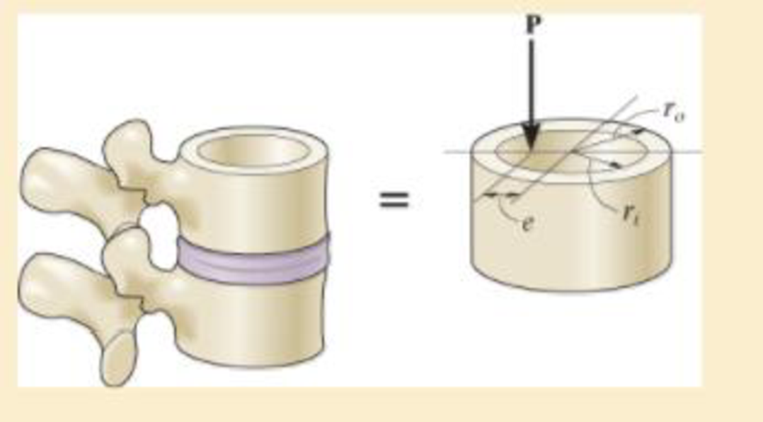
Determine the smallest force P that can be applied to a vertebra, if we assume this load is applied at an eccentric distance e from the centerline of the bone, and the bone remains elastic. Model the vertebra as a hollow cylinder with an inner radius ri and outer radius ro.
Expert Solution & Answer
Want to see the full answer?
Check out a sample textbook solution
Students have asked these similar questions
The vertebra of the spinal column can support a maximum compressive stress of smax, before undergoing a compression fracture. Determine the smallest force P that can be applied to a vertebra, if we assume this load is applied at an eccentric distance e from the centerline of the bone, and the bone remains elastic. Model the vertebra as a hollow cylinder with an inner radius ri and outer radius ro.
The rigid lever arm is supported by two A-36 steel wires having the same diameter of 4 mm. Determine the smallest force P that will cause (a) only one of the wires to yield; (b) both wires to yield. Consider A-36 steel as anelastic perfectly plastic material.
A tensile force of 100 kN is applied on a 0.02-m diameter and 2-m long rod. After applying the load, the diameter of the rod decreases to 0.01998 m and the length increases to2.01 m. The true axialstrain is?
Chapter 8 Solutions
MECHANICS OF MATERIALS
Ch. 8.1 - If it is subjected to an internal pressure of p =...Ch. 8.1 - If it is subjected to an internal pressure of p =...Ch. 8.1 - The thin-walled cylinder can be supported in one...Ch. 8.1 - If the inner diameter of the tank is 22 in., and...Ch. 8.1 - Air pressure in the cylinder is increased by...Ch. 8.1 - Determine the maximum force P that can be exerted...Ch. 8.1 - A boiler is constructed of 8-mm-thick steel plates...Ch. 8.1 - 88. The steel water pipe has an inner diameter of...Ch. 8.1 - The steel water pipe has an inner diameter of 12...Ch. 8.1 - The A-36-steel band is 2 in. wide and is secured...
Ch. 8.1 - The gas pipe line is supported every 20 ft by...Ch. 8.1 - A pressure-vessel head is fabricated by welding...Ch. 8.1 - An A-36-steel hoop has an inner diameter of 23.99...Ch. 8.1 - The ring, having the dimensions shown, is placed...Ch. 8.1 - The inner ring A has an inner radius r1 and outer...Ch. 8.1 - Two hemispheres having an inner radius of 2 ft and...Ch. 8.1 - In order to increase the strength of the pressure...Ch. 8.2 - Show the results on the left segment.Ch. 8.2 - Show the stress that each of these loads produce...Ch. 8.2 - Fundamental Problems F81. Determine the normal...Ch. 8.2 - Show the results in a differential element at the...Ch. 8.2 - Determine the state of stress at point A on the...Ch. 8.2 - Determine the magnitude of the load P that will...Ch. 8.2 - Determine the state of stress at point B. Show the...Ch. 8.2 - Determine the state of stress at point A on the...Ch. 8.2 - Determine the state of stress at point A on the...Ch. 8.2 - Show the results in a differential element at the...Ch. 8.2 - Determine the shortest distance d to the edge of...Ch. 8.2 - The plate has a thickness of 20 mm and P acts...Ch. 8.2 - Plot the distribution of normal stress acting...Ch. 8.2 - Also, plot the normal-stress distribution over the...Ch. 8.2 - If the allowable normal stress for the steel is...Ch. 8.2 - If the applied force P = 1.50 kip, determine the...Ch. 8.2 - Determine the maximum normal stress on the cross...Ch. 8.2 - If the wood has an allowable normal stress of...Ch. 8.2 - Determine the maximum normal stress along section...Ch. 8.2 - Sketch the stress distribution along section aa of...Ch. 8.2 - Sketch the normal-stress distribution acting over...Ch. 8.2 - Determine the state of stress at points A and B,...Ch. 8.2 - If the force of 100 N is applied to the handles,...Ch. 8.2 - Determine the stress components at point A on the...Ch. 8.2 - Determine the stress components at point B on the...Ch. 8.2 - Determine the normal stress developed at points A...Ch. 8.2 - Sketch the normal-stress distribution acting over...Ch. 8.2 - Determine the state of stress at points A and B,...Ch. 8.2 - Determine the state of stress at point A on the...Ch. 8.2 - Determine the state of stress at point B on the...Ch. 8.2 - Determine the state of stress acting at point D....Ch. 8.2 - Determine the state of stress acting at point E....Ch. 8.2 - If it is subjected to the force system shown,...Ch. 8.2 - Solve Prob.840 for point B.Ch. 8.2 - Determine the stress components acting on the...Ch. 8.2 - Determine the stress components acting on the...Ch. 8.2 - Neglect the weight of the block.Ch. 8.2 - Neglect the weight of the block.Ch. 8.2 - He is supported uniformly by two bars, each having...Ch. 8.2 - Determine the state of stress at point A, and show...Ch. 8.2 - Determine the state of stress at point B, and show...Ch. 8.2 - Determine the state of stress at point C, and show...Ch. 8.2 - Determine the maximum radius e at which the load P...Ch. 8.2 - Specify the region to which this load can be...Ch. 8.2 - Determine the smallest force P that can be applied...Ch. 8.2 - The coiled spring is subjected to a force P. If we...Ch. 8.2 - The pins at C and D are at the same location as...Ch. 8.2 - Determine the state of stress at point A, and show...Ch. 8.2 - Determine the state of stress at point B, and show...Ch. 8.2 - Determine the stress components at points A and B...Ch. 8.2 - Determine the stress components at points C and D...Ch. 8.2 - Determine the stress components in the support...Ch. 8.2 - Determine the stress components in the support...Ch. 8.2 - If the force at the ram on the clamp at D is P= 8...Ch. 8.2 - Determine the maximum ram force P that can be...Ch. 8.2 - and an outer radius of 3.00 in. If the face of the...Ch. 8.2 - for points E and F.Ch. 8.2 - Determine the stress components at points A and B...Ch. 8.2 - Solve Prob.8-65 for points C and D.Ch. 8.2 - Due to internal gearing, this causes the block to...Ch. 8.2 - Determine the state of stress at point A and show...Ch. 8.2 - Solve Prob.868 for point B.Ch. 8.2 - Determine the stress components at point A. Sketch...Ch. 8.2 - for the stress components at point B.Ch. 8.2 - Determine the state of stress at point A at...Ch. 8.2 - Determine the state of stress at point B at...Ch. 8 - If it supports a cable loading of 800 lb,...Ch. 8 - Determine the state of stress at point E on the...Ch. 8 - Determine the state of stress at point F on the...Ch. 8 - The suspender arm AE has a square cross-sectional...Ch. 8 - If the cross section of the femur at section aa...Ch. 8 - If it has a mass of 5 kg/m, determine the largest...Ch. 8 - and is used to support the vertical reactions of...Ch. 8 - and is used to support the vertical reactions of...
Knowledge Booster


Learn more about
Need a deep-dive on the concept behind this application? Look no further. Learn more about this topic, mechanical-engineering and related others by exploring similar questions and additional content below.Similar questions
- The stepped rod is made up of two different materials A and B of lengths 80 cm and 1.2 m respectively. The diameters of materials B and A are 2.5 and 3.5 cm respectively. The modulus of elasticity of materials A and B are 250 and 150 GPa respectively. The elongation of the rod is the same for both the materials. A total tensile load of 40 kN is applied to both the materials A and B together. Calculate the load in each material.arrow_forwardThe armor shown supports loads of 3 KN. The horizontal elements are 713cm long each. Determine the axial force on element FE; Use the section method to determine the axial force in the FE element and check your result with the nodal or joint method. INFO: Y= 100 cmarrow_forwardFour 10 kg masses are being supported by an 800mm solid rod. The rod is being supported at both ends, and the rest of the rod is suspended. Determine the smallest rod diameter to support the masses without bending the rod. Assume the Tensile Strength of the Rod material is 500 MPaarrow_forward
- How can we determine the maximum axial force P that can beapplied to the bar?arrow_forwardCompound axial member ABC has a uniform diameter of d-2.4 in. Segment (1) is an aluminum [E₁ - 10,000 ksi] alloy and segment (2) is a copper [E₂ - 17,000 ksi] alloy. The lengths of segments (1) and (2) are L₁ - 78 in. and L₂ - 150 in., respectively. Determine the force P required to stretch compound member ABC by a total of 0.35 in. L₁ A Part 1 Aluminum Answer: A- B Save for Later Calculate the cross-sectional area of the compound member. L2 (2) Copper in.² C P Attempts: 0 of 1 used Submit Answer Part 2 The parts of this question must be completed in order. This part will be available when you complete the part above. Part 3 The parts of this question must be completed in order. This part will be available when you complete the part above.arrow_forwardA bar, 12 mm in diameter is acted upon by an axial load of 20 kN. The change in diameter is measured as 0.03 mm. DeterminePoisson’s ratioYoung’s modulusBulk modulus Assume modulus of rigidity as 80 GPaarrow_forward
- Compound axial member ABC has a uniform diameter of d = 2.9 in. Segment (1) is an aluminum [E₁ = 10,000 ksi] alloy and segment (2) is a copper [E₂ = 17,000 ksi] alloy. The lengths of segments (1) and (2) are L₁ = 90 in. and L₂ = 130 in., respectively. Determine the force P required to stretch compound member ABC by a total of 0.30 in. L₁ P L2 Aluminum B Copper CP A Answer: P= i kipsarrow_forwardCompound axial member ABC has a uniform diameter of d = 2.9 in. Segment (1) is an aluminum [E₁ = 10,000 ksi] alloy and segment (2) is a copper [E₂ = 17,000 ksi] alloy. The lengths of segments (1) and (2) are L₁ = 80 in. and L₂ = 110 in., respectively. Determine the force P required to stretch compound member ABC by a total of 0.10 in. A Li (1) Aluminum B L2 (2) Copperarrow_forwardA football (soccer) player can kick the ball with about 4 kN of force. Suppose an athlete accidentally kicks their competitor's tibia instead of the ball. This injury may be modeled by the diagram below, where the kick is represented by force F. Assume that the load is applied directly in the middle of the tibia. For the sake of simplicity, model the bone as a solid beam with 2 cm x 2 cm square cross-sectional area. Note that the pin and roller in the model do not induce reaction moments. Use E = 16 GPa. F = 500 N/cm 20 cm (a) Draw a free body diagram (FBD) including all external forces.arrow_forward
- Compound axial member ABC has a uniform diameter of d = 1.0 in. Segment (1) is an aluminum [E1 = 10,000 ksi] alloy and segment (2) is a copper [E2 = 17,000 ksi] alloy. The lengths of segments (1) and (2) are L1 = 66 in. and L2 = 110 in., respectively. Determine the force P required to stretch compound member ABC by a total of 0.45 in. L1 L2 (1) A d Aluminum (2) В Соpper Answer: kips P = iarrow_forwardThe blue bar is made from steel with the following mechanical properties: Young's Modulus, E = 17x10° psi; Poisson's Ratio v = 0.31. The bar has a circular cross-section with diameter d= 0.50 in. being the length of each side. 557 lb 557 Ib 60 in. - Determine the following under the action of the axial load (assume elastic behavior): a. The bar's axial deformation, ô, in in.: b. The average axial or longitudinal strain, ELong: c. The change in the bar's diameter, in in.:arrow_forward2-1. A standard steel specimen of in. dia- meter elongated 0.0087 in. in an 8 in. gage length when it was subjected to a tensile force of 6,250 lb. If the specimen was known to be in the elastic range, what is the elastic modulus of the steel? Ans: 29.3 x 10⁶ psi.arrow_forward
arrow_back_ios
SEE MORE QUESTIONS
arrow_forward_ios
Recommended textbooks for you
 Elements Of ElectromagneticsMechanical EngineeringISBN:9780190698614Author:Sadiku, Matthew N. O.Publisher:Oxford University Press
 Mechanics of Materials (10th Edition)Mechanical EngineeringISBN:9780134319650Author:Russell C. HibbelerPublisher:PEARSON
 Thermodynamics: An Engineering ApproachMechanical EngineeringISBN:9781259822674Author:Yunus A. Cengel Dr., Michael A. BolesPublisher:McGraw-Hill Education
 Control Systems EngineeringMechanical EngineeringISBN:9781118170519Author:Norman S. NisePublisher:WILEY
 Mechanics of Materials (MindTap Course List)Mechanical EngineeringISBN:9781337093347Author:Barry J. Goodno, James M. GerePublisher:Cengage Learning
 Engineering Mechanics: StaticsMechanical EngineeringISBN:9781118807330Author:James L. Meriam, L. G. Kraige, J. N. BoltonPublisher:WILEY
Elements Of Electromagnetics
Mechanical Engineering
ISBN:9780190698614
Author:Sadiku, Matthew N. O.
Publisher:Oxford University Press
Mechanics of Materials (10th Edition)
Mechanical Engineering
ISBN:9780134319650
Author:Russell C. Hibbeler
Publisher:PEARSON
Thermodynamics: An Engineering Approach
Mechanical Engineering
ISBN:9781259822674
Author:Yunus A. Cengel Dr., Michael A. Boles
Publisher:McGraw-Hill Education
Control Systems Engineering
Mechanical Engineering
ISBN:9781118170519
Author:Norman S. Nise
Publisher:WILEY
Mechanics of Materials (MindTap Course List)
Mechanical Engineering
ISBN:9781337093347
Author:Barry J. Goodno, James M. Gere
Publisher:Cengage Learning
Engineering Mechanics: Statics
Mechanical Engineering
ISBN:9781118807330
Author:James L. Meriam, L. G. Kraige, J. N. Bolton
Publisher:WILEY
Engineering Basics - Statics & Forces in Equilibrium; Author: Solid Solutions - Professional Design Solutions;https://www.youtube.com/watch?v=dQBvQ2hJZFg;License: Standard YouTube License, CC-BY