
MECHANICS OF MATERIALS
10th Edition
ISBN: 2818440034374
Author: HIBBELER
Publisher: PEARSON
expand_more
expand_more
format_list_bulleted
Concept explainers
Videos
Textbook Question
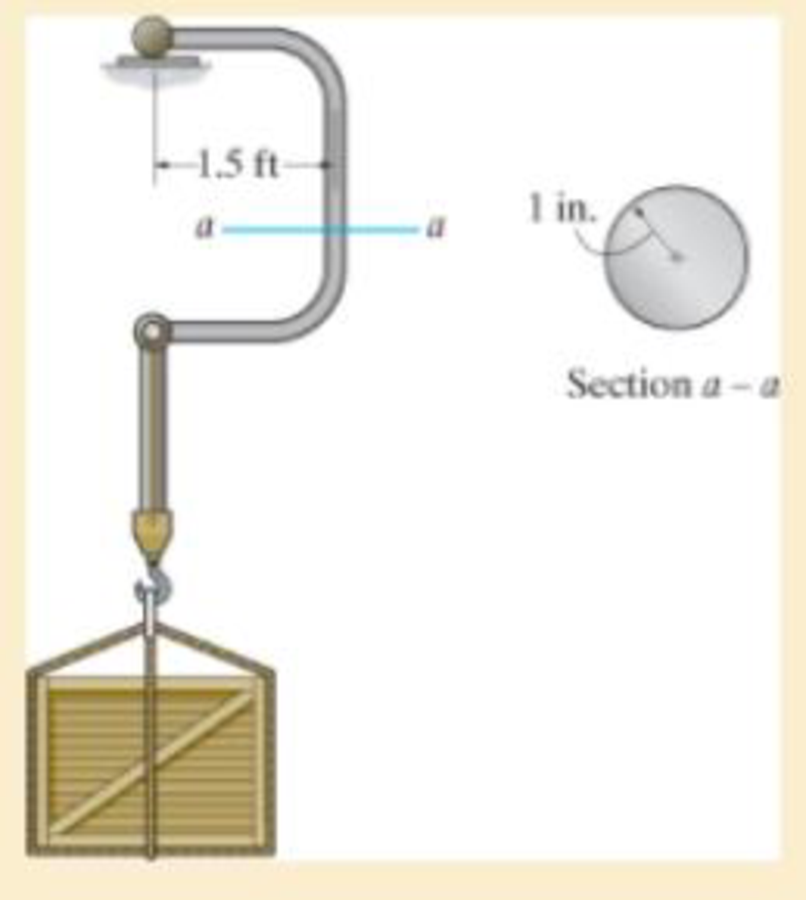
Chapter 8.2, Problem 8.21P
Also, plot the normal-stress distribution over the cross section.
Expert Solution & Answer

Trending nowThis is a popular solution!

Students have asked these similar questions
Two blocks joined by a single pin are subjected to a pulling force of P = 250 Ib. The pin has a diameter of 0.25 in and the
dimensions of the blocks with respect to the figure below are listed below.
a = 2.42 in
b = 1.52 in
C = 1.5 in
ti = 0.89 in
t2 = 1.2 in
Note that the dimensions b and c represent the distance from the edge of the block to the middle of the pin
t, 1
a
Vinter201920-Engr220-001/images/9de8f780-b478-3fb6-91f7-bd1015381538_fafc4bb4-e5d
Image is not drawn to scale.
Calculate non-zero stress components (normal and shear) at points A, B
and C. Point C is located at the center of the cross section attached to
the wall. Calculate non-zero strain components at point B.
Neglect shear stress due to shear force.
Given:
loading F
=
400 N, P-2000 N, and T = 75 N·m,
Young's modulus E = 70 GPa, Poisson's ratio v = 0.25
15-mm D.
-100 mm
Derive the relationship between critical resolved shear stress and disloca-
tion density given below
Terss = To + AVPD
Chapter 8 Solutions
MECHANICS OF MATERIALS
Ch. 8.1 - If it is subjected to an internal pressure of p =...Ch. 8.1 - If it is subjected to an internal pressure of p =...Ch. 8.1 - The thin-walled cylinder can be supported in one...Ch. 8.1 - If the inner diameter of the tank is 22 in., and...Ch. 8.1 - Air pressure in the cylinder is increased by...Ch. 8.1 - Determine the maximum force P that can be exerted...Ch. 8.1 - A boiler is constructed of 8-mm-thick steel plates...Ch. 8.1 - 88. The steel water pipe has an inner diameter of...Ch. 8.1 - The steel water pipe has an inner diameter of 12...Ch. 8.1 - The A-36-steel band is 2 in. wide and is secured...
Ch. 8.1 - The gas pipe line is supported every 20 ft by...Ch. 8.1 - A pressure-vessel head is fabricated by welding...Ch. 8.1 - An A-36-steel hoop has an inner diameter of 23.99...Ch. 8.1 - The ring, having the dimensions shown, is placed...Ch. 8.1 - The inner ring A has an inner radius r1 and outer...Ch. 8.1 - Two hemispheres having an inner radius of 2 ft and...Ch. 8.1 - In order to increase the strength of the pressure...Ch. 8.2 - Show the results on the left segment.Ch. 8.2 - Show the stress that each of these loads produce...Ch. 8.2 - Fundamental Problems F81. Determine the normal...Ch. 8.2 - Show the results in a differential element at the...Ch. 8.2 - Determine the state of stress at point A on the...Ch. 8.2 - Determine the magnitude of the load P that will...Ch. 8.2 - Determine the state of stress at point B. Show the...Ch. 8.2 - Determine the state of stress at point A on the...Ch. 8.2 - Determine the state of stress at point A on the...Ch. 8.2 - Show the results in a differential element at the...Ch. 8.2 - Determine the shortest distance d to the edge of...Ch. 8.2 - The plate has a thickness of 20 mm and P acts...Ch. 8.2 - Plot the distribution of normal stress acting...Ch. 8.2 - Also, plot the normal-stress distribution over the...Ch. 8.2 - If the allowable normal stress for the steel is...Ch. 8.2 - If the applied force P = 1.50 kip, determine the...Ch. 8.2 - Determine the maximum normal stress on the cross...Ch. 8.2 - If the wood has an allowable normal stress of...Ch. 8.2 - Determine the maximum normal stress along section...Ch. 8.2 - Sketch the stress distribution along section aa of...Ch. 8.2 - Sketch the normal-stress distribution acting over...Ch. 8.2 - Determine the state of stress at points A and B,...Ch. 8.2 - If the force of 100 N is applied to the handles,...Ch. 8.2 - Determine the stress components at point A on the...Ch. 8.2 - Determine the stress components at point B on the...Ch. 8.2 - Determine the normal stress developed at points A...Ch. 8.2 - Sketch the normal-stress distribution acting over...Ch. 8.2 - Determine the state of stress at points A and B,...Ch. 8.2 - Determine the state of stress at point A on the...Ch. 8.2 - Determine the state of stress at point B on the...Ch. 8.2 - Determine the state of stress acting at point D....Ch. 8.2 - Determine the state of stress acting at point E....Ch. 8.2 - If it is subjected to the force system shown,...Ch. 8.2 - Solve Prob.840 for point B.Ch. 8.2 - Determine the stress components acting on the...Ch. 8.2 - Determine the stress components acting on the...Ch. 8.2 - Neglect the weight of the block.Ch. 8.2 - Neglect the weight of the block.Ch. 8.2 - He is supported uniformly by two bars, each having...Ch. 8.2 - Determine the state of stress at point A, and show...Ch. 8.2 - Determine the state of stress at point B, and show...Ch. 8.2 - Determine the state of stress at point C, and show...Ch. 8.2 - Determine the maximum radius e at which the load P...Ch. 8.2 - Specify the region to which this load can be...Ch. 8.2 - Determine the smallest force P that can be applied...Ch. 8.2 - The coiled spring is subjected to a force P. If we...Ch. 8.2 - The pins at C and D are at the same location as...Ch. 8.2 - Determine the state of stress at point A, and show...Ch. 8.2 - Determine the state of stress at point B, and show...Ch. 8.2 - Determine the stress components at points A and B...Ch. 8.2 - Determine the stress components at points C and D...Ch. 8.2 - Determine the stress components in the support...Ch. 8.2 - Determine the stress components in the support...Ch. 8.2 - If the force at the ram on the clamp at D is P= 8...Ch. 8.2 - Determine the maximum ram force P that can be...Ch. 8.2 - and an outer radius of 3.00 in. If the face of the...Ch. 8.2 - for points E and F.Ch. 8.2 - Determine the stress components at points A and B...Ch. 8.2 - Solve Prob.8-65 for points C and D.Ch. 8.2 - Due to internal gearing, this causes the block to...Ch. 8.2 - Determine the state of stress at point A and show...Ch. 8.2 - Solve Prob.868 for point B.Ch. 8.2 - Determine the stress components at point A. Sketch...Ch. 8.2 - for the stress components at point B.Ch. 8.2 - Determine the state of stress at point A at...Ch. 8.2 - Determine the state of stress at point B at...Ch. 8 - If it supports a cable loading of 800 lb,...Ch. 8 - Determine the state of stress at point E on the...Ch. 8 - Determine the state of stress at point F on the...Ch. 8 - The suspender arm AE has a square cross-sectional...Ch. 8 - If the cross section of the femur at section aa...Ch. 8 - If it has a mass of 5 kg/m, determine the largest...Ch. 8 - and is used to support the vertical reactions of...Ch. 8 - and is used to support the vertical reactions of...
Knowledge Booster


Learn more about
Need a deep-dive on the concept behind this application? Look no further. Learn more about this topic, mechanical-engineering and related others by exploring similar questions and additional content below.Similar questions
- Determine the maximum tensile and compressive stresses in portion BC of the beam, under loading conditions of two vertical forces that applied on it. The beam has cross section as shown in figure. 100KN | 100KN 200 mm 25 mm 25 mm 150 um 25 mm 1500 mm 500 mm 500 mm 100 mmarrow_forwardDraw Mohr's circle for the state of stress defined by 01= 80 MPa, o2 = -20 MPa and t12= 40 MPa. (1 points) %3Darrow_forwardFor the bar in the way the loading status is seen determine the strain energy on the rod so that the shear stress on the rod is maximum 120 MPa.( Part of BC is hollow)arrow_forward
- YU Fixed end 4.25 KN.m 0.3m 5KN · 100 KN 100 KN 0.4 m 3.0 KN-m 5 KN 200 KN 200KN 0.1 m X Find the axial, torsional, bending and transverse shear stresses at the four critical points (top, bottom, left and right) of the central cross section. Draw the stress state cubes and then represent them as plane stress states, if applicable. This stainless steel beam has a circular cross section and a diameter of 7 centemeterarrow_forwardP to point A of the section given in the figure Plot the normal stress distribution in the section, given that a compressive force of = 20 kN is applied.arrow_forward10 The stress components at a point are given by: Ox = Oy = 0z = 50 MPa, try = 10, tv = 20, t = 15 MPa. %3D Calculate the strain components. Take E = 200 GPa and v = 0-30. %3D %3Darrow_forward
- The book is subjected to the force of 60 lb Determine the state of stress at point A at section a-a. The cross section is circular and has a diameter of 0.5 in. Use the curved-beam formula to compute the bending stress (Figure 1) Figure 1.5 in. 13 45° B 1 of 1 > ▾ Part A Determine the normal stress. Express your answer using three significant figures and include the appropriate units. Enter negative value in the case of compression and positive value in the case of tension. g= Value Submit Part B ← A psi Previous Answers Request Answer X Incorrect; Try Again; 4 attempts remaining ✓ Correct < Return to Assignment Ċ 129 ? Determine the shear stress Express your answer using three significant figures and include the appropriate units. T= 0 psi Previous Answers Provide Feedbackarrow_forwardFill in the blanks. Draw and label the Mohr’s circle. For sigma-yp = 30 kSf. does this fail? Find the stresses on the plane shown. Find the plane on which sigma-1 acts relative to the horizontal. Draw them on the figure. Draw the Tresca plot.arrow_forwardFind normal stress . Take d=1.1 mmarrow_forward
- A simply supported wood beam is subjected to uniformly distributed load q. The width of the beam is 6 in, and the height is 8 in. Determine the normal stress and the shear stress at point C. Show these stresses on a sketch of a stress element at point C.arrow_forwardUsing the Maximum Strain Criterion, determine the uniaxial failure stress, Ox, for off-axis loading of the unidirectional laminar in Fig. if the material is AS/3501 graphite/epoxy and the angle 0=30 .arrow_forward69. A disc of 600 mm diameter and uniform thickness is rotating at 3000 rpm. Calculate the maximum stress developed in the disc. If a hole of 100 mm dianmeter is drilled at the centre of the disc, then determine maximum radial and hoop stresses developed. Take vs 0-28 and p = 7800 kg/m.arrow_forward
arrow_back_ios
SEE MORE QUESTIONS
arrow_forward_ios
Recommended textbooks for you
 Elements Of ElectromagneticsMechanical EngineeringISBN:9780190698614Author:Sadiku, Matthew N. O.Publisher:Oxford University Press
 Mechanics of Materials (10th Edition)Mechanical EngineeringISBN:9780134319650Author:Russell C. HibbelerPublisher:PEARSON
 Thermodynamics: An Engineering ApproachMechanical EngineeringISBN:9781259822674Author:Yunus A. Cengel Dr., Michael A. BolesPublisher:McGraw-Hill Education
 Control Systems EngineeringMechanical EngineeringISBN:9781118170519Author:Norman S. NisePublisher:WILEY
 Mechanics of Materials (MindTap Course List)Mechanical EngineeringISBN:9781337093347Author:Barry J. Goodno, James M. GerePublisher:Cengage Learning
 Engineering Mechanics: StaticsMechanical EngineeringISBN:9781118807330Author:James L. Meriam, L. G. Kraige, J. N. BoltonPublisher:WILEY
Elements Of Electromagnetics
Mechanical Engineering
ISBN:9780190698614
Author:Sadiku, Matthew N. O.
Publisher:Oxford University Press
Mechanics of Materials (10th Edition)
Mechanical Engineering
ISBN:9780134319650
Author:Russell C. Hibbeler
Publisher:PEARSON
Thermodynamics: An Engineering Approach
Mechanical Engineering
ISBN:9781259822674
Author:Yunus A. Cengel Dr., Michael A. Boles
Publisher:McGraw-Hill Education
Control Systems Engineering
Mechanical Engineering
ISBN:9781118170519
Author:Norman S. Nise
Publisher:WILEY
Mechanics of Materials (MindTap Course List)
Mechanical Engineering
ISBN:9781337093347
Author:Barry J. Goodno, James M. Gere
Publisher:Cengage Learning
Engineering Mechanics: Statics
Mechanical Engineering
ISBN:9781118807330
Author:James L. Meriam, L. G. Kraige, J. N. Bolton
Publisher:WILEY
Understanding Stress Transformation and Mohr's Circle; Author: The Efficient Engineer;https://www.youtube.com/watch?v=_DH3546mSCM;License: Standard youtube license