
Videos
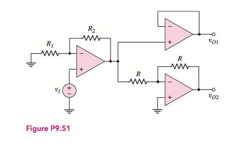
(a) Consider the ideal op-amp circuit shown in Figure P9.51. Determine thevoltage gains
(a)
The expression for the voltage gain
Answer to Problem 9.51P
The relation between the voltage
Explanation of Solution
Calculation:
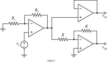
The given diagram is shown in Figure 1
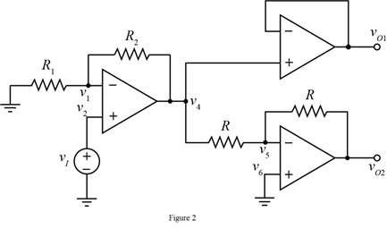
Mark the voltages in the above circuit.
The required diagram is shown in Figure 2
The expression for the value of the voltage gain of first amplifier is given by,
The expression for the value of the voltage gain of second amplifier is given by,
The expression for the value of the voltage
The expression for the value of the voltage
The expression for the voltage
The expression for the voltage
The expression for the voltage
Substitute
The expression for the value of the voltage
Substitute
Apply KCL at node
Substitute
Substitute
Substitute
Apply KVL at node
Substitute
Substitute
Substitute
From above and from equation (1) the relation between the voltage
Conclusion:
Therefore, the relation between the voltage
(b)
The value of the voltage
Answer to Problem 9.51P
The value of the output voltage
Explanation of Solution
Calculation:
The expression for the value of voltage
Substitute
The expression for the value of the voltage
Substitute
Conclusion:
Therefore, the value of the output voltage
(c)
The value of the difference
Answer to Problem 9.51P
The value of the difference of voltage
Explanation of Solution
Calculation:
The expression for the difference
Substitute
Conclusion:
Therefore, the value of the difference of voltage
Want to see more full solutions like this?
Chapter 9 Solutions
Microelectronics: Circuit Analysis and Design


- 3D Problem 1. (P1) Three op-amps are connected in cascade configuration. An 80 microVolts signal is connected to the non-inverting input of the first op-amp. Both the 2nd and 3rd op-amps operates as inverting amplifiers. All feedback resistors are 420 KOhms while the input resistances are 71.4kOhms, 19.1kOhms, and 14KOhms respectively. Determine the output of the third stage stage. a.9 V b.9000 mV c.79.2 V d.792 mVarrow_forwardGiven circuit, assume op-amp is ideal. What is the input resistance of the circuit, RIN? What are the currents in the inputs of op-amp? i-=? i+=? What is the output resistance of the circuit, ROUT=? Find voltage VA and VB? What is the nodal equation (KCL) at node VB? Solve for VOUT=?arrow_forwardDerive the following. Assume an ideal current source c) Output Impedancearrow_forward
- 1. PLEASE SOLVE AND SHOW YOUR DETAILED SOLUTION WITH FBD. A parallel circuit consisting of a resistor, an impedance coil, and a capacitor of negligible loss is connected across a 120-volt 25-Hz supply and takes a current of 4.3 amp. The current to the resistor is 3.6amp, that of the capacitor 2.5 amp, and that to the impedance coil, 3.2 amp, Determine the power-factor angle and power of the entire circuit.arrow_forwardWhat is the concept of linearization process of nonlinear damper and how it is done? Cite sourcearrow_forwardGiven the circuit below, please solve for the ff: a. What is the configuration of the given amplifier circuit below?b. How are the coupling capacitors treated in the figure at AC?Please show your clean and complete solutionarrow_forward
- Given the following details: The inverting adder schematic as seen below Vac is an AC voltage source which generates a sine waveform with amplitude 1mV and frequency 1kHz Vout is a sine waveform with amplitude 1V and has a DC offset of 3.5V Find the values of Vdc, R1, R2 and Rf that would satisfy the description for Vout. Assume ideal scenario (i.e. do theoretical computations instead of practical simulations)arrow_forwardWhen Itspice simulation of the circuit shown in the figure is performed, which of the following figures is the output representation (Vout) as given? NOTE-1: Vcc = 12 V, RO = 2.2 kO, RB 15S kO, RE 180 0 and C11 uF. NOTE-2: For the input voltage Vin, the DC offset voltage is 1.6 V, while the applied sinusoidal signal has a amplitude of 10 mV and a frequency of 10 kHz.arrow_forwardA coil of resistance 20 Ω and inductance 300 mH is connected in parallel with a capacitor of 200μF. A variable frequency supply of 110 V is provided to the connection. Find the value of the frequency for the condition that the current drawn from the supply is in phase with the source voltage. Find the value of dynamic resistance and current for this conditionarrow_forward
- a. At what frequency is the gain equal to 0 dB? (in Mrad/sec)b. At what range of frequencies is the phase equal to 90∘? (in form: Mrad/sec ≤ ω ≤ Mrad/sec)arrow_forwardSubject : ELECTRONIC CIRCUIT ANALYSIS AND DEVICES Please give the DC ANALYSIS CIRCUIT and AC EQUIVALENT CIRCUIT of this problem before proceeding to find letter c. (Note : Neglect Vbe)arrow_forwardNEED ASAP Show the op-amp circuit diagramarrow_forward
 Introductory Circuit Analysis (13th Edition)Electrical EngineeringISBN:9780133923605Author:Robert L. BoylestadPublisher:PEARSON
 Delmar's Standard Textbook Of ElectricityElectrical EngineeringISBN:9781337900348Author:Stephen L. HermanPublisher:Cengage Learning
 Programmable Logic ControllersElectrical EngineeringISBN:9780073373843Author:Frank D. PetruzellaPublisher:McGraw-Hill Education
 Fundamentals of Electric CircuitsElectrical EngineeringISBN:9780078028229Author:Charles K Alexander, Matthew SadikuPublisher:McGraw-Hill Education
 Electric Circuits. (11th Edition)Electrical EngineeringISBN:9780134746968Author:James W. Nilsson, Susan RiedelPublisher:PEARSON
 Engineering ElectromagneticsElectrical EngineeringISBN:9780078028151Author:Hayt, William H. (william Hart), Jr, BUCK, John A.Publisher:Mcgraw-hill Education,