
Concept explainers
Videos
Refer to the two magnetically coupled coils of Fig. 13.69(a). The polarity of the mutual voltage is:
- (a) Positive
- (b) Negative
Figure 13.69
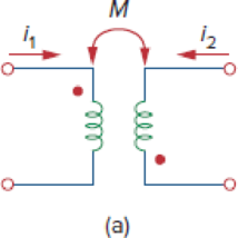
Choose the correct option, which is the polarity of the mutual voltage.
Answer to Problem 1RQ
The correct option from the given choices is
Explanation of Solution
Given data:
Refer to Figure 13.69(a) in the textbook for the two magnetically coupled coils.
Calculation:
Modify the Figure 13.69(a) by indicating positive and negative terminals and mentioning coils 1 and 2. The modified figure as shown in Figure 1.
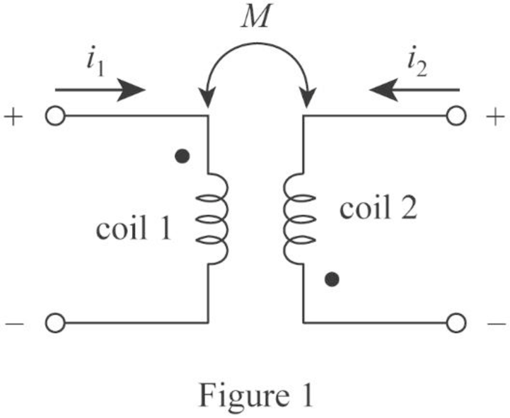
Consider that the currents are denoted as
In Figure 13.69(a), the current
Similarly, the current leaves at the dotted terminal of coil 2 and the voltage is positive in the dotted terminal of coil 1. Hence, the mutual voltage
Therefore, the polarity of mutual voltage is negative. Hence, the option (b) is correct and option (a) is incorrect.
Conclusion:
Thus, the correct option from the given choices is
Want to see more full solutions like this?
Chapter 13 Solutions
Fundamentals of Electric Circuits
Additional Engineering Textbook Solutions
Microelectronics: Circuit Analysis and Design
Introductory Circuit Analysis (13th Edition)
Electric Circuits (10th Edition)
Basic Engineering Circuit Analysis
Principles and Applications of Electrical Engineering
Electric machinery fundamentals


- Calculate the equivalent impedance of a circuit in which a coil of wire having a value of 5∠53.2ºohm is connected in parallel with a capacitive reactance of 6.25 ohms.arrow_forwardCalculate the voltage at the terminals of a coil of resistance 10 ohms and inductance 15H at the instant when the current is 12A amd increasing at the rate of 6A/sec.arrow_forwardElectrical engineering A 375 kVA, 6600/400 V, 3-phase core type transformer has a total loss of 3700 watts on full load. The transformer tank is 1.25 m in height and 1 m × 0.5 m in plan. Design a suitable scheme for cooling tubes if the average temperature rise is to be limited to 35 °C. The diameter of the tube is 50 mm and are spaced 75 mm from each other. The average height of the tube is 1.05 m.arrow_forward
- DESIGN A CONVENTIONAL POWER SUPPLY USING 220V AC , 10 KILO OHMS RESISTOR ,4 SILICON DIODES, CAPACITOR , TRANSFORMER WITH 20:1 TURNS' RATIO AND PERCENTAGE ERROR= 5 PERCENT. FIND THE SUITABLE REGULATORarrow_forwardCalculate the mesh currents in the circuit of Fig. 13.11.arrow_forwardFor a star connection network, consuming power of 1.8kW and power factor 0.5, compute the inductance and resistance of each coil at a supply voltage of 230 Volts, 60 Hzarrow_forward
- A coil has an inductance of 40 mH and negligible resistance. Calculate its inductive reactance and the resulting current if connected to (a) a 240V, 50 Hz supply, and (b) a 100V, 1 kHz supplyarrow_forwardA 10 kVA, 500/250 V, single phase transformer has its maximum efficiency of 94% when delivering 90% of its rated output at unity p.t. Estimate its efficiency when delivering its full load output at p.t. of 0.8 lagging.3arrow_forward11. Two coupled coils have self-inductances L1 = 2 H and L2 = 0.5 H, and a coefficient of coupling K = 0.9. Determine the turns ratio N1/N2 of the two coils.arrow_forward
- "A single coil 800 turns instrument transformer, operating in the step-downs mode with a 25 percent tap, supplies a 10 kVA, 0.80 power factor lagging load. The input to the transformer is 6600 V, 50 Hz. Assume that leakage effects and minor losses in transformer are negligible. Determine the following : (i) Turn ratio; (ii) Load current(in Amp); (iii) Incoming line current(in Amp); (iv) Transformed current (in Amp); (v) Apparent power conducted(in kVA)and (vi) Apparent power transformed"arrow_forwardTwo coupled coils have inductance of L1 = 0.8 H and L2 = 0.2 H, respectively. If the coefficient of coupling is 0.75, find the turns ratio N1/N2 for the coils. Show Solution Pleasearrow_forwardCompute L in millihenries based on the given parameters for the industrial coil circuit. and Determine R if: E = 196 VV1 = 67 VVO = 105 V Note: Round your answer to 4 decimal places.arrow_forward
 Introductory Circuit Analysis (13th Edition)Electrical EngineeringISBN:9780133923605Author:Robert L. BoylestadPublisher:PEARSON
 Delmar's Standard Textbook Of ElectricityElectrical EngineeringISBN:9781337900348Author:Stephen L. HermanPublisher:Cengage Learning
 Programmable Logic ControllersElectrical EngineeringISBN:9780073373843Author:Frank D. PetruzellaPublisher:McGraw-Hill Education
 Fundamentals of Electric CircuitsElectrical EngineeringISBN:9780078028229Author:Charles K Alexander, Matthew SadikuPublisher:McGraw-Hill Education
 Electric Circuits. (11th Edition)Electrical EngineeringISBN:9780134746968Author:James W. Nilsson, Susan RiedelPublisher:PEARSON
 Engineering ElectromagneticsElectrical EngineeringISBN:9780078028151Author:Hayt, William H. (william Hart), Jr, BUCK, John A.Publisher:Mcgraw-hill Education,