Fundamentals of Electric Circuits
6th Edition
ISBN: 9780078028229
Author: Charles K Alexander, Matthew Sadiku
Publisher: McGraw-Hill Education
bartleby

Videos

Textbook Question
Book Icon
Chapter 13, Problem 20P

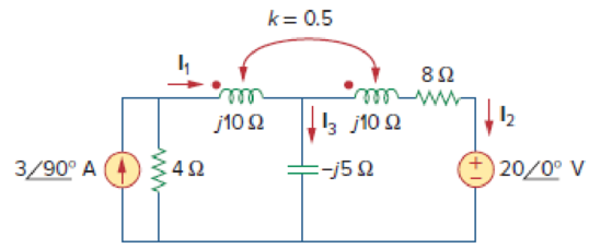
Determine currents I1, I2, and I3 in the circuit of Fig. 13.89. Find the energy stored in the coupled coils at t = 2 ms. Take ω = 1,000 rad/s.

Chapter 13, Problem 20P, Determine currents I1, I2, and I3 in the circuit of Fig. 13.89. Find the energy stored in the

Expert Solution & Answer
Check Mark
To determine

Calculate the currents I1,I2,andI3 in the coupled coils circuit in Figure 13.89 and calculate the stored energy in the coupled coils at t=2ms.

Answer to Problem 20P

The currents I1,I2,andI3 are 2.46272.18°A_, 0.87897.48°A_, and 3.32974.89°A_ respectively. The energy stored in the coupled coils is 43.67mJ_.

Explanation of Solution

Given data:

Refer to Figure 13.89 in the textbook for the circuit with coupled coils.

The value of ω is 1,000rad/s. The coupling coefficient is 0.5.

Calculation:

Calculate the mutual inductance in frequency domain.

jM=jk(10)(10)=j0.5100{k=0.5}=j5Ω

Modify the Figure 13.89 by transforming the current source (390°A=j3A) with parallel resistor (4Ω) is converted into the voltage source (j3A×4Ω=j12V) with series resistor (4Ω). The modified circuit as shown in Figure 1.

Fundamentals of Electric Circuits, Chapter 13, Problem 20P

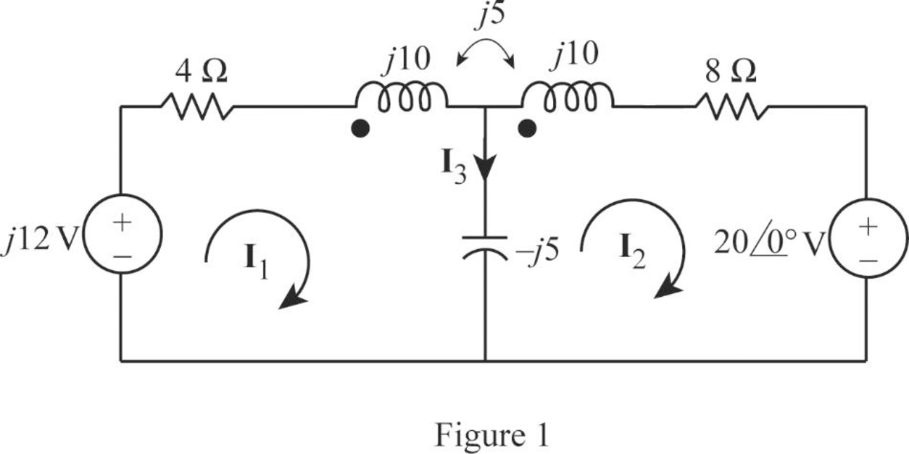
From Figure 1, consider that the loops 1 and 2 contain the currents I1 and I2 respectively.

Apply Kirchhoff's voltage law to the loop 1 in Figure 1.

(4+j10j5)I1+j5I2+j5I2=j12

(4+j5)I1+j10I2=j12        (1)

Apply Kirchhoff's voltage law to the loop 2 in Figure 1.

20+(8+j10j5)I2+j5I1+j5I1=0

j10I1+(8+j5)I2=20        (2)

Write equations (1) and (2) in matrix form as follows.

[(4+j5)j10j10(8+j5)][I1I2]=[j1220]        (3)

Write the MATLAB code to solve the equation (3).

A = [(4+j*5) j*10;j*10 (8+j*5)];

B = [j*12; -20];

C = inv(A)*B

The output in command window:

C =

   0.75354 + 2.34381i

  -0.11429 - 0.87049i

From the MATLAB output, the currents I1 and I2 are,

I1=(0.75354+j2.34381)A=2.46272.18°A

And

I2=(0.11429j0.87049)A=0.87897.48°A

From Figure 1, consider the expression for the current I3.

I3=I1I2

Substitute (0.75354+j2.34381)A for I1 and (0.11429j0.87049)A for I2.

I3=(0.75354+j2.34381)A(0.11429j0.87049)A=0.86783+j3.2143=3.32974.89°A

Write the current I1 and I2 in time-domain.

i1=2.462cos(1000t+72.18°)A        (4)

i2=0.878cos(1000t97.48°)A        (5)

Substitute 2 ms for t in Equation (4).

i1=2.462cos(1000(2ms)+72.18°)A=2.462cos((2rad)+72.18°)A=2.462cos(114.6°+72.18°)A{2rad=2×180πdeg=114.6°}=2.445A

Substitute 2 ms for t in Equation (5).

i2=0.878cos(1000(2ms)97.48°)A=0.878cos((2rad)97.48°)A=0.878cos(114.6°97.48°)A{2rad=2×180πdeg=114.6°}=0.8391A

From Figure 13.81, find the inductor values.

Calculate the inductor L1.

ωL1=10

Substitute 1000 for ω.

(1000)L1=10L1=0.01H

Calculate the inductor L2.

ωL2=10

Substitute 1000 for ω.

(1000)L2=10L2=0.01H

And

Calculate the mutual inductance.

M=0.5L1

Substitute 0.01 H for L1.

M=0.5(0.01H)=0.005H

Write the expression for the total energy stored in the coupled coils.

w=0.5L1i12+0.5L2i22+Mi1i2

Substitute 0.01 H for L1, 0.01 H for L2, 0.005 H for M, 2.445A for i1, 0.8391A for i2

w=0.5(0.01)(2.445)2+0.5(0.01)(0.8391)2+0.005(2.445)(0.8391)=(29.89×10³)+(3.5204×10³)+(10.258×10³)=43.67×10³J=43.67mJ

Conclusion:

Thus, the currents I1,I2,andI3 are 2.46272.18°A_, 0.87897.48°A_, and 3.32974.89°A_ respectively. The energy stored in the coupled coils is 43.67mJ_.

Want to see more full solutions like this?

Subscribe now to access step-by-step solutions to millions of textbook problems written by subject matter experts!
Students have asked these similar questions
Calculate the energy stored in the coupled coils at t = 10 ms if M = 0.2 H and vs =  12 cos 10t V.
single coil 600 turns instrument transformer, operating in the step-down mode with a 40 percent tap, supplies a 5 kVA, 0.88 power factor inductive load. The input to the transformer is 3.3 kV, 50 Hz. Assume that leakage effects and minor losses in transformer are negligible. Determine the following : (0) Turn ratio; (ii) Load current(in Amp); (iii) Incoming line current(in Amp); (iv) Transformed current (in Amp); (v) Apparent power conducted(in kVA)and (vi) Apparent power transformed"
Given a 115kV/13.2kV distribution transformer rated at 30MVA with an 8% nameplate impedance what is the full Load current in amps

Chapter 13 Solutions

Fundamentals of Electric Circuits

Ch. 13.6 - In the autotransformer circuit of Fig. 13.45, find...Ch. 13.7 - Prob. 12PPCh. 13.8 - Prob. 13PPCh. 13.9 - Refer to Fig. 13.61. Calculate the turns ratio...Ch. 13.9 - Calculate the turns ratio of an ideal transformer...Ch. 13.9 - In Example 13.17, if the eight 100-W bulbs are...Ch. 13 - Refer to the two magnetically coupled coils of...Ch. 13 - Prob. 2RQCh. 13 - Prob. 3RQCh. 13 - Prob. 4RQCh. 13 - The ideal transformer in Fig. 13.70(a) has N2/N1 =...Ch. 13 - Prob. 6RQCh. 13 - A three-winding transformer is connected as...Ch. 13 - Prob. 8RQCh. 13 - Prob. 9RQCh. 13 - Prob. 10RQCh. 13 - For the three coupled coils in Fig. 13.72,...Ch. 13 - Using Fig. 13.73, design a problem to help other...Ch. 13 - Two coils connected in series-aiding fashion have...Ch. 13 - (a) For the coupled coils in Fig. 13.74(a), show...Ch. 13 - Two coils are mutually coupled, with L1 = 50 mH,...Ch. 13 - Given the circuit shown in Fig. 13.75, determine...Ch. 13 - For the circuit in Fig. 13.76, find Vo. Figure...Ch. 13 - Find v(t) for the circuit in Fig. 13.77.Ch. 13 - Prob. 9PCh. 13 - Find vo in the circuit of Fig. 13.79. Figure 13.79...Ch. 13 - Use mesh analysis to find ix in Fig. 13.80, where...Ch. 13 - Determine the equivalent Leq in the circuit of...Ch. 13 - For the circuit in Fig. 13.82, determine the...Ch. 13 - Obtain the Thevenin equivalent circuit for the...Ch. 13 - Find the Norton equivalent for the circuit in Fig....Ch. 13 - Obtain the Norton equivalent at terminals a-b of...Ch. 13 - In the circuit of Fig. 13.86, ZL is a 15-mH...Ch. 13 - Find the Thevenin equivalent to the left of the...Ch. 13 - Determine an equivalent T-section that can be used...Ch. 13 - Determine currents I1, I2, and I3 in the circuit...Ch. 13 - Prob. 21PCh. 13 - Find current Io in the circuit of Fig. 13.91.Ch. 13 - Let is = 5 cos (100t) A. Calculate the voltage...Ch. 13 - In the circuit of Fig. 13.93, (a) find the...Ch. 13 - Prob. 25PCh. 13 - Find Io in the circuit of Fig. 13.95. Switch the...Ch. 13 - Find the average power delivered to the 50-...Ch. 13 - In the circuit of Fig. 13.97, find the value of X...Ch. 13 - Prob. 29PCh. 13 - (a) Find the input impedance of the circuit in...Ch. 13 - Using Fig. 13.100, design a problem to help other...Ch. 13 - Two linear transformers are cascaded as shown in...Ch. 13 - Determine the input impedance of the air-core...Ch. 13 - Using Fig. 13.103, design a problem to help other...Ch. 13 - Find currents I1, I2, and I3 in the circuit of...Ch. 13 - As done in Fig. 13.33, obtain the relationships...Ch. 13 - A 2402,400-V rms step-up ideal transformer...Ch. 13 - Design a problem to help other students better...Ch. 13 - A 1,200240-V rms transformer has impedance on the...Ch. 13 - The primary of an ideal transformer with a turns...Ch. 13 - Given I2 = 2 A, determine the value of Is in Fig....Ch. 13 - For the circuit in Fig. 13.107, determine the...Ch. 13 - Obtain V1 and V2 in the ideal transformer circuit...Ch. 13 - In the ideal transformer circuit of Fig. 13.109,...Ch. 13 - For the circuit in Fig. 13.110, find the value of...Ch. 13 - (a) Find I1 and I2 in the circuit of Fig. 13.111...Ch. 13 - Prob. 47PCh. 13 - Using Fig. 13.113, design a problem to help other...Ch. 13 - Find current ix in the ideal transformer circuit...Ch. 13 - Prob. 50PCh. 13 - Use the concept of reflected impedance to find the...Ch. 13 - For the circuit in Fig. 13.117, determine the...Ch. 13 - Refer to the network in Fig. 13.118. (a) Find n...Ch. 13 - A transformer is used to match an amplifier with...Ch. 13 - For the circuit in Fig. 13.120, calculate the...Ch. 13 - Find the power absorbed by the 100- resistor in...Ch. 13 - For the ideal transformer circuit of Fig. 13.122...Ch. 13 - Determine the average power absorbed by each...Ch. 13 - In the circuit of Fig. 13.124, let vs = 165...Ch. 13 - Refer to the circuit in Fig. 13.125 on the...Ch. 13 - For the circuit in Fig. 13.126, find Il, I2, and...Ch. 13 - For the network in Fig. 13.127, find: (a) the...Ch. 13 - Find the mesh currents in th circuit of Fig....Ch. 13 - For the circuit in Fig. 13.129. find the turns...Ch. 13 - Calculate the average power dissipated by the 20-...Ch. 13 - Design a problem to help other students better...Ch. 13 - An autotransformer with a 40 percent tap is...Ch. 13 - In the ideal autotransformer of Fig. 13.131,...Ch. 13 - In the circuit of Fig. 13.131, N1 = 190 turns and...Ch. 13 - In the ideal transformer circuit shown in Fig....Ch. 13 - When individuals travel, their electrical...Ch. 13 - In order to meet an emergency, three single-phase...Ch. 13 - Figure 13.135 on the next page shows a three-phase...Ch. 13 - Consider the three-phase transformer shown in Fig....Ch. 13 - A balanced three-phase transformer bank with the...Ch. 13 - Using Fig. 13.138, design a problem to help other...Ch. 13 - The three-phase system of a town distributes power...Ch. 13 - Use PSpice or MultiSim to determine the mesh...Ch. 13 - Use PSpice or MultiSim to find I1, I2, and I3 in...Ch. 13 - Prob. 80PCh. 13 - Use PSpice or MultiSim to find I1, I2, and I3 in...Ch. 13 - A stereo amplifier circuit with ail output...Ch. 13 - A transformer having 2,400 turns on the primary...Ch. 13 - A radio receiver has an input resistance of 300 ....Ch. 13 - A step-down power transformer with a turns ratio...Ch. 13 - A 240120-V rms power transformer is rated at 10...Ch. 13 - A 4-kVA, 2,400240-V rms transformer has 250 turns...Ch. 13 - A 25,000240-V rms distribution transformer has a...Ch. 13 - A 4,800-V rms transmission line feeds a...Ch. 13 - A four-winding transformer (Fig. 13.146) is often...Ch. 13 - A 440/110-V ideal transformer can be connected to...Ch. 13 - Ten bulbs in parallel are supplied by a 7,200120-V...
Knowledge Booster
Background pattern image
Electrical Engineering
Learn more about
Need a deep-dive on the concept behind this application? Look no further. Learn more about this topic, electrical-engineering and related others by exploring similar questions and additional content below.
Similar questions
SEE MORE QUESTIONS
Recommended textbooks for you
Text book image
Introductory Circuit Analysis (13th Edition)
Electrical Engineering
ISBN:9780133923605
Author:Robert L. Boylestad
Publisher:PEARSON
Text book image
Delmar's Standard Textbook Of Electricity
Electrical Engineering
ISBN:9781337900348
Author:Stephen L. Herman
Publisher:Cengage Learning
Text book image
Programmable Logic Controllers
Electrical Engineering
ISBN:9780073373843
Author:Frank D. Petruzella
Publisher:McGraw-Hill Education
Text book image
Fundamentals of Electric Circuits
Electrical Engineering
ISBN:9780078028229
Author:Charles K Alexander, Matthew Sadiku
Publisher:McGraw-Hill Education
Text book image
Electric Circuits. (11th Edition)
Electrical Engineering
ISBN:9780134746968
Author:James W. Nilsson, Susan Riedel
Publisher:PEARSON
Text book image
Engineering Electromagnetics
Electrical Engineering
ISBN:9780078028151
Author:Hayt, William H. (william Hart), Jr, BUCK, John A.
Publisher:Mcgraw-hill Education,
Mesh Current Problems in Circuit Analysis - Electrical Circuits Crash Course - Beginners Electronics; Author: Math and Science;https://www.youtube.com/watch?v=DYg8B-ElK0s;License: Standard Youtube License