
Calculate the coupling coefficient of the circuit that make the
Answer to Problem 29P
The required coupling coefficient is
Explanation of Solution
Given data:
Refer to Figure 13.98 in the textbook for the circuit with coupled coils.
In Figure 13.98, consider that the primary and secondary loops contain the currents
The value of
The value of
Calculation:
Calculate the inductors in frequency domain.
Write the expression for the inductive reactance.
Substitute 30 mH for
Substitute 50 mH for
Consider that the value of X.
Substitute
Consider that the second side reflect on the primary side. Consider the expression for the input impedance.
Write the expression for the current
Substitute 330 V for V and Equation (3) in (4).
Consider the expression for the power dissipated in the
Substitute 1.288 kW for p.
Substitute 16 A for
Square on both sides of the equation.
Simplify the equation as follows.
By solving the above equation, there are two positive values of X and they are,
Consider that the value of X as 38.128.
Substitute 38.128 for X in Equation (2).
Consider the expression for the coefficient of coupling in the coupled coils.
Substitute 38.128 mH for M, 30 mH for
Modify the Figure 13.98 by transforming the time-domain circuit with coupled-coils to frequency domain of the circuit with coupled-coils. The frequency domain equivalent circuit is shown in Figure 1.
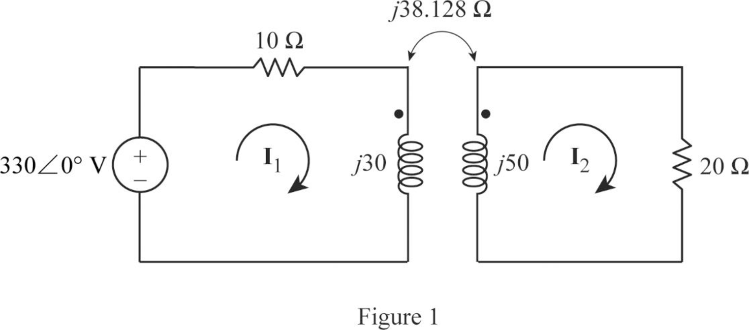
From Figure 1, consider that the loops 1 and 2 contain the currents
Apply Kirchhoff's voltage law to the loop 1 in Figure 1.
Apply Kirchhoff's voltage law to the loop 2 in Figure 1.
Write equations (6) and (7) in matrix form as follows.
Write the MATLAB code to solve the equation (8).
A = [(10+j*30) j*(-38.128); j*(-38.128) (20+j*50)];
B = [330; 0];
I = inv(A)*B
The output in command window:
I =
15.535 - 3.829i
11.219 + 1.568i
From the MATLAB output, the currents
And
Write the currents
Substitute 1.5 ms for t in Equation (9).
Substitute 1.5 ms for t in Equation (10).
Write the expression for the total energy stored in the coupled coils.
Substitute 30 mH for
Conclusion:
Thus, the required coupling coefficient is
Want to see more full solutions like this?
Chapter 13 Solutions
Fundamentals of Electric Circuits

- Given a 115kV/13.2kV distribution transformer rated at 30MVA with an 8% nameplate impedance what is the full Load current in ampsarrow_forwardsingle coil 600 turns instrument transformer, operating in the step-down mode with a 40 percent tap, supplies a 5 kVA, 0.88 power factor inductive load. The input to the transformer is 3.3 kV, 50 Hz. Assume that leakage effects and minor losses in transformer are negligible. Determine the following : (0) Turn ratio; (ii) Load current(in Amp); (iii) Incoming line current(in Amp); (iv) Transformed current (in Amp); (v) Apparent power conducted(in kVA)and (vi) Apparent power transformed"arrow_forward11. Two coupled coils have self-inductances L1 = 2 H and L2 = 0.5 H, and a coefficient of coupling K = 0.9. Determine the turns ratio N1/N2 of the two coils.arrow_forward
- A 10 kVA, 500/250 V, single phase transformer has its maximum efficiency of 94% when delivering 90% of its rated output at unity p.t. Estimate its efficiency when delivering its full load output at p.t. of 0.8 lagging.3arrow_forward3. Calculate the full-load primary and secondary currents of a 5 kVA, 2400/120 V, transformer. Subject: Electrical Apparatus and Devicesarrow_forwardCalculate the equivalent impedance of a circuit in which a coil of wire having a value of 5∠53.2ºohm is connected in parallel with a capacitive reactance of 6.25 ohms.arrow_forward
- A transformer has 440 primary windings and 22 secondary windings. The potential difference across the primary coil is 100 V. The secondary coil is connected across a 125-ohm resistor. Find (a) secondary current (b) primary current. Hint: Use conservation of power. (c) effective load resistance of the SECONDARY COIL, which is connected across a 125 ohm resistor.arrow_forwardA 2,400/480-V rms step-down ideal transformer delivers 50 kW to a resistive load. Calculate:(a) the turns ratio(b) the primary current(c) the secondary currentarrow_forwardAn industrial plant is powered with a delta delta system, along with a transformer bank made up of single-phase transformers of 20KVA, 2300/230 V each. The bank supplies a 40 KVA load with a power factor of 0.7 (-). If a damaged transformer is removed for repair, calculate:a) The load in KVA that each transformer has.b) The nominal load of the transformer bank W.arrow_forward
- A 2300/230 V distribution transformer is delivering a load of 50 kW to a certain part of a community. If the total wire impedance is .05 Ω, what power is actually dellvered? Ans. 47.64 kWarrow_forwardCalculate the equivalent impedance of a circuit where a coil of (5H, angle 53.2 Deg.) ohms is connected in parallel with a capacitive reactance of 6.25 ohms.arrow_forward10. In a 25KVA, 2000 / 200 V power transformer, the iron and full load copper losses are 350W and 400W respectively. Calculate the efficiency at unity power factor at (i) full load and (ii) half load.arrow_forward
 Introductory Circuit Analysis (13th Edition)Electrical EngineeringISBN:9780133923605Author:Robert L. BoylestadPublisher:PEARSON
 Delmar's Standard Textbook Of ElectricityElectrical EngineeringISBN:9781337900348Author:Stephen L. HermanPublisher:Cengage Learning
 Programmable Logic ControllersElectrical EngineeringISBN:9780073373843Author:Frank D. PetruzellaPublisher:McGraw-Hill Education
 Fundamentals of Electric CircuitsElectrical EngineeringISBN:9780078028229Author:Charles K Alexander, Matthew SadikuPublisher:McGraw-Hill Education
 Electric Circuits. (11th Edition)Electrical EngineeringISBN:9780134746968Author:James W. Nilsson, Susan RiedelPublisher:PEARSON
 Engineering ElectromagneticsElectrical EngineeringISBN:9780078028151Author:Hayt, William H. (william Hart), Jr, BUCK, John A.Publisher:Mcgraw-hill Education,