
Videos
A finite-element model of a cantilever beam subject to loading and moments (Fig. P16.15) is given by optimizing
where
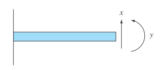
FIGURE P16.15
A cantilever beam.
Want to see the full answer?
Check out a sample textbook solution
Chapter 16 Solutions
EBK NUMERICAL METHODS FOR ENGINEERS


- Beams, Shear Force and Bending Moment in Beams Problem#3: HOMEWORK Draw Shear Force and Moment diagram II 100lbs 100lbs 2 1 3 5 6 Ra Rbarrow_forwardc) Calculate the equations of internal shear force V(x) and bending moment M(x). Type the mathematical expressions or constants, following the defined sign convection. Section AB: Internal shear force equation: V(x) = Internal bending moment equation: M(x) : Section BC: Internal shear force equation: V(x) Internal bending moment equation: M(x) = = N N N*mm N*mmarrow_forwardFor the simply-supported and cantilever beams given below, use Singularity Functions to determine slope and displacement equations. Provide graphs of both slope and displacement versus position along the beam. A A 5 ft B * B 5 ft 5 ft 27 kips E 20 ft 45 kip-ft 11 kips 5 ft 3.5 kips/ft 20 ft C 5 ft 5 ft 2.3 kips/ft 5 ft ]c S ft Darrow_forward
- Q3. Fig Q3 shows a uniform cantilever beam of length L which is loaded by a linearly varying load: w(x) = wo where w is the load per unit length at the fixed end (x =0). L w(x) Fig Q3: A uniform cantilever beam (a) Using Ritz method, derive a two-term polynomial function to approximate the transverse displacement (u) of the beam. Total potential energy (TPE) for a beam under bending load is: TPE= EI d'u Jo 2 dx² -w(x)u dx where E is Young's modulus and I is second moment of area. (b) Calculate the bending moment at x = L based on Ritz solution.arrow_forwardA rectangular tube of outer width w = 7.5 m, outer height h = 5 m and thickness t = 0.17 m experiences bending through the x axis. What is the moment of inertia of the cross-sectional area In? y -- X MATLAB input variables: format shortEng W = 7.5; h = 5; t = 0.17; moment of inertia I, = m4arrow_forwardUse the graphical method to construct the shear-force and bending-moment diagrams for the beam shown. Let a=3.5 ft, b=9.0 ft, c=4.0 ft, d=3.5 ft, w = 5.5 kips/ft and P = 45 kips. Construct the shear-force and bending-moment diagrams on paper and use the results to answer the questions in the subsequent parts of this GO exercise. For this loading, calculate the reaction forces Ay and Ey acting on the beam. Positive values for the reactions are indicated by the directions of the red arrows shown on the free-body diagram below. (Note: Since Ax = 0, it has been omitted from the free-body diagram.) Ay =___________ kips, Ey = __________ kips. Determine the shear force acting at each of the following locations:(a) x = 0+ ft (i.e., just to the right of support A)(b) x = 3.5 ft(c) x = 12.5 ft(d) x = 16.5– ft (i.e., just to the left of D)(e) x = 16.5+ ft (i.e., just to the right of D)(f) x = 20.0– ft (i.e., just to the left of support E) Answer: a to f ) V = ________ kips Use the graphical…arrow_forward
- During a bicep curl on a bicep curl machine, I'm curling a weight stack of 100 pounds (single arm...I'm jacked like that). At this very moment, the weight stack has a moment arm of 0.12m, my elbow has an angle of 63deg, my muscle force vector has an angle of 23deg, and it attaches 3cm below my elbow joint on my radius. How much force must my bicep create right at this moment to hold the weight stack in place?arrow_forwardUse the graphical method to construct the shear-force and bending-moment diagrams for the beam shown. Let a= 3.5 ft, b= 8.0 ft, t, c= 5.0 ft, d= 3.0 ft, w = 8.5 kips/ft and P = 54 kips. Construct the shear-force and bending-moment diagrams on paper and use the results to answer the questions in the subsequent parts of this GO exercise. P В D E b d Calculate the maximum bending moment (i.e., either positive or negative) that occurs between points B and C. When entering your answers, use the bending moment sign convention. Answers: M = i kip-ft.arrow_forwardUse the graphical method to construct the shear-force and bending-moment diagrams for the beam shown. Let a= 3.5 ft, b= 8.0 ft, t, c= 5.0 ft, d= 3.0 ft, w = 8.5 kips/ft and P = 54 kips. Construct the shear-force and bending-moment diagrams on paper and use the results to answer the questions in the subsequent parts of this GO exercise. P В D E d The shear-force diagram crosses the V = 0 axis between points B and C. Determine the location x (measured from A) where V = 0 kips. Answer: x = i ft.arrow_forward
- Use the graphical method to construct the shear-force and bending-moment diagrams for the beam shown. Let a= 3.5 ft, b= 8.0 ft, t, c= 5.0 ft, d= 3.0 ft, w = 8.5 kips/ft and P = 54 kips. Construct the shear-force and bending-moment diagrams on paper and use the results to answer the questions in the subsequent parts of this GO exercise. P В D E d Use the graphical method to determine the bending moment acting at B (i.e., x = 3.5 ft). When entering your answers, use the bending moment sign convention. Answer: MB = i kip-ft.arrow_forwardUse the graphical method to construct the shear-force and bending-moment diagrams for the beam shown. Let a= 3.5 ft, b= 8.0 ft, t, c= 5.0 ft, d= 3.0 ft, w = 8.5 kips/ft and P = 54 kips. Construct the shear-force and bending-moment diagrams on paper and use the results to answer the questions in the subsequent parts of this GO exercise. P В D E a d Determine the shear force acting at each of the following locations: (a) x = 0+ ft (i.e., just to the right of support A) (b) x = 3.5 ft (c) x = 11.5 ft (d) x = 16.5- ft (i.e., just to the left of D) (e) x = 16.5+ ft (i.e., just to the right of D) (f) x = 19.5- ft (i.e., just to the left of support E) When entering your answers, use the shear force sign convention. Answers: (a) V = i kips. (b) V - i kips. (c) V= i kips. (d) V = i kips. (e) V = i kips. (f) V = i kips.arrow_forwardUse the graphical method to construct the shear-force and bending-moment diagrams for the beam shown. Let a= 3.5 ft, b= 8.0 ft, t, c= 5.0 ft, d= 3.0 ft, w = 8.5 kips/ft and P = 54 kips. Construct the shear-force and bending-moment diagrams on paper and use the results to answer the questions in the subsequent parts of this GO exercise. P В D E b d For this loading, calculate the reaction forces A, and E, acting on the beam. Positive values for the reactions are indicated by the directions of the red arrows shown on the free-body diagram below. (Note: Since A = 0, it has been omitted from the free-body diagram.) P B C E b d E, Answers: Ay = i kips, Ey = i kips.arrow_forward
 Elements Of ElectromagneticsMechanical EngineeringISBN:9780190698614Author:Sadiku, Matthew N. O.Publisher:Oxford University Press
 Mechanics of Materials (10th Edition)Mechanical EngineeringISBN:9780134319650Author:Russell C. HibbelerPublisher:PEARSON
 Thermodynamics: An Engineering ApproachMechanical EngineeringISBN:9781259822674Author:Yunus A. Cengel Dr., Michael A. BolesPublisher:McGraw-Hill Education
 Control Systems EngineeringMechanical EngineeringISBN:9781118170519Author:Norman S. NisePublisher:WILEY
 Mechanics of Materials (MindTap Course List)Mechanical EngineeringISBN:9781337093347Author:Barry J. Goodno, James M. GerePublisher:Cengage Learning
 Engineering Mechanics: StaticsMechanical EngineeringISBN:9781118807330Author:James L. Meriam, L. G. Kraige, J. N. BoltonPublisher:WILEY