
Concept explainers
Videos
Each of the double pulleys shown has a mass moment of inertia of 15 lb·ft·s2 and is initially at rest. The outside radius is 18 in., and the inner radius is 9 in. Determine (a) the angular acceleration of each pulley, (b) the angular velocity of each pulley after point A on the cord has moved 10 ft.
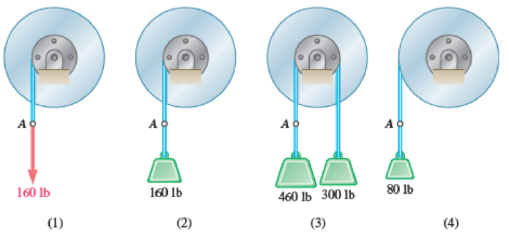
Fig. P16.34
(a)
Find the angular acceleration of the pulley 1
Find the angular acceleration of the pulley 2
Find the angular acceleration of the pulley 3
Find the angular acceleration of the pulley 4
Answer to Problem 16.34P
The angular acceleration of the pulley 1
The angular acceleration of the pulley 2
The angular acceleration of the pulley 3
The angular acceleration of the pulley 4
Explanation of Solution
The mass moment of inertia of the double pulleys
The outside radius of the pulley
The inner radius of the pulley
The finial angular velocity of the pulley
The load of the pulley 1
The load of the pulley 2
The left side load of the pulley 3
The right side load of the pulley 3
The load of the pulley 4
Calculation:
Consider the acceleration due to gravity (g) is
Case 1:
Convert the unit of the outside radius
Convert the unit of the inner radius
Show the free body diagram of the double pulley 1 as in Figure 1.
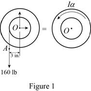
Here,
Refer to Figure 1.
Calculate the angular acceleration of the pulley 1
Calculate the moment about point O by applying the equation of equilibrium:
Hence, the angular acceleration of the pulley 1
Case 2:
Calculate the mass of the pulley 2
Substitute
Show the free body diagram of the double pulley 2 as in Figure 2.
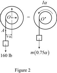
Refer to Figure 2.
Calculate the moment about point O by applying the equation of equilibrium:
Calculate the angular acceleration of the pulley 2
Substitute
Hence, the angular acceleration of the pulley 2
Case 3:
Calculate the left side mass of the pulley 3
Substitute
Calculate the right side mass of the pulley 3
Substitute
Show the free body diagram of the double pulley 3 as in Figure 3.
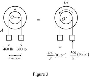
Refer to Figure 3.
Calculate the moment about point O by applying the equation of equilibrium:
Calculate the angular acceleration of the pulley 3
Substitute
Hence, the angular acceleration of the pulley 3
Case 4:
Calculate the left side mass of the pulley 4
Substitute
Show the free body diagram of the double pulley 4 as in Figure 4.
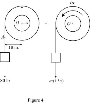
Refer to Figure 4.
Calculate the moment about point O by applying the equation of equilibrium:
Calculate the angular acceleration of the pulley 4
Substitute
Hence, the angular acceleration of the pulley 4
(b)
Find the angular velocity of the pulley 1
Find the angular velocity of the pulley 2
Find the angular velocity of the pulley 3
Find the angular velocity of the pulley 4
Answer to Problem 16.34P
The angular velocity of the pulley 1
The angular velocity of the pulley 2
The angular velocity of the pulley 3
The angular velocity of the pulley 4
Explanation of Solution
The mass moment of inertia of the double pulleys
The outside radius of the pulley
The inner radius of the pulley
The finial angular velocity of the pulley
The load of the pulley 1
The load of the pulley 2
The left side load of the pulley 3
The right side load of the pulley 3
The load of the pulley 4
The moved distance of the point A (l) is
Calculation:
Refer part (a).
Case 1:
Calculate the angle of the pulley 1
Substitute
Calculate the angular velocity of the pulley 1
Substitute
Hence, the angular velocity of the pulley 1
Case 2:
Calculate the angle of the pulley 2
Substitute
Calculate the angular velocity of the pulley 2
Substitute
Hence, the angular velocity of the pulley 2
Case 3:
Calculate the angle of the pulley 3
Substitute
Calculate the angular velocity of the pulley 3
Substitute
Hence, the angular velocity of the pulley 3
Case 4:
Calculate the angle of the pulley 4
Substitute
Calculate the angular velocity of the pulley 4
Substitute
Hence, the angular velocity of the pulley 4
Want to see more full solutions like this?
Chapter 16 Solutions
Vector Mechanics for Engineers: Statics and Dynamics
Additional Engineering Textbook Solutions
Fundamentals Of Thermodynamics
Mechanics of Materials (10th Edition)
Heating Ventilating and Air Conditioning: Analysis and Design
Heat and Mass Transfer: Fundamentals and Applications
HEAT+MASS TRANSFER:FUND.+APPL.
Machine Elements in Mechanical Design (6th Edition) (What's New in Trades & Technology)


- The rotor of an electric motor has an angular velocity of 3600 rpm when the load and power are cut off. The 110-lb rotor, which has a centroidal radius of gyration of 9 in., then coasts to rest. Knowing that the kinetic friction of the rotor produces a couple with a magnitude of 2.5 1b.ft determine the number of revolutions that the rotor executes before coming to rest.arrow_forwardA 3-kg bar AB is attached by a pin at D to a 4-kg square plate, which can rotate freely about a vertical axis. Knowing that the angular velocity of the plate is 120 rpm when the bar is vertical, determine (a ) the angular velocity of the plate after the bar has swung into a horizontal position and has come to rest against pin C, (b) the energy lost during the plastic impact at C.arrow_forwardThe 8-in. radius brake drum is attached to a larger flywheel that is not shown. The total mass moment of inertia of the drum and the flywheel is 15 lb.ft.s2 and the coefficient of kinetic friction between the drum and the brake shoe is 0.40. Knowing that the angular velocity of the flywheel is 450 rpm clockwise when a force P of magnitude 65 lbf. is applied to the pedal C, determine the number of the revolutions executed by the flywheel before it comes to rest. (The final answer should be in two decimal places with correct units)arrow_forward
- The shutter shown was formed by removing one quarter of a disk of 0.75-in. radius and is used to interrupt a beam of light emanating from a lens at C. Knowing that the shutter weighs 0.125 lb and rotates at the constant rate of 24 cycles per second, determine the magnitude of the force exerted by the shutter on the shaft at Aarrow_forwardEach of the gears A and B has a mass of 675 g and a radius of gyration of 40 mm, while gear C has a mass of 3.6 kg and a radius of gyration of 100 mm. Assume that kinetic friction in the bearings of gears A, B C produces couples of constant magnitude 0.15 N.m, 0.15 N.m, 0.3 N.m, respectively. Knowing that the initial angular velocity of gear C is 2000 rpm, determine the time required for the system to come to rest.arrow_forwardDisk A, of weight 10 lb and radius r = 6 in., is at rest when it is placed in contact with belt BC, which moves to the right with a constant speed v = 40 ft/s. Knowing that μk = 0.20 between the disk and the belt, determine the number of revolutions executed by the disk before it attains a constant angular velocity.arrow_forward
- The 10-in.-radius brake drum is attached to a larger flywheel which is not shown. The total mass moment of inertia of the flywheel and drum is 22 lb ⋅ ft ⋅ s 2 and the coefficient of kinetic friction between the drum and the brake shoe is 0.41. Knowing that the initial angular velocity is 255 rpm clockwise, determine the force which must be exerted by the hydraulic cylinder at point B if the system is to stop in 85 revolutions. DO NOT ROUND OFF IN THE SOLUTION. ROUND OFF ONLY THE FINAL ANSWERarrow_forwardThe 10-in.-radius brake drum is attached to a larger flywheel which is not shown. The total mass moment of inertia of the flywheel and drum is 22 lb ⋅ ft ⋅ s 2 and the coefficient of kinetic friction between the drum and the brake shoe is 0.41. Knowing that the initial angular velocity is 255 rpm clockwise, determine the force which must be exerted by the hydraulic cylinder at point B if the system is to stop in 85 revolutions.arrow_forwardIn order to determine the mass moment of inertia of a flywheel of radius 600 mm, a 12-kg block is attached to a wire that is wrapped around the flywheel. The block is released and is observed to fall 3 m in 4.6 s. To eliminate bearing friction from the computation, a second block of mass 24 kg is used and is observed to fall 3 m in 3.1 s. Assuming that the moment of the couple due to friction remains constant, determine the mass moment of inertia of the flywheel.arrow_forward
- The mechanism shown is one of two identical mechanisms attached to the two sides of a 200-lb uniform rectangular door. Edge ABC of the door is guided by wheels of negligible mass that roll in horizontal and vertical tracks. A spring with a constant k is attached to wheel B in such a way that its tension is zero when 0 = 30°, Knowing that the door is released from rest in the position 0 = 45° and reaches the vertical position with an angular velocity of 0.6 rad/s, determine the spring constant k.arrow_forwardIn the gear arrangement shown, gears A and C are attached to rod ABC, that is free to rotate about B, while the inner gear B is fixed. Knowing that the system is at rest, determine the magnitude of the couple M that must be applied to rod ABC, if 2.5 s later the angular velocity of the rod is to be 240 rpm clockwise. Gears A and C ABC weighs 4 lb.arrow_forwardThe upper and lower ends of the arms are pivoted on the axis of the governor has equal arms of length 44cm. The extension arms of the lower links are each 10cm long and parallel to the axis.When the governor at minimum and maximum position, the radii of rotation of the balls are 17cm and 24cm respectively. The mass of each ball is 10 kg and the mass of the central load is 102 kg. Determine : 1.The range of angular speed of the governor and identify the type of governor 2.Draw the line diagram when the governor at minimum and maximum positionarrow_forward
 Elements Of ElectromagneticsMechanical EngineeringISBN:9780190698614Author:Sadiku, Matthew N. O.Publisher:Oxford University Press
 Mechanics of Materials (10th Edition)Mechanical EngineeringISBN:9780134319650Author:Russell C. HibbelerPublisher:PEARSON
 Thermodynamics: An Engineering ApproachMechanical EngineeringISBN:9781259822674Author:Yunus A. Cengel Dr., Michael A. BolesPublisher:McGraw-Hill Education
 Control Systems EngineeringMechanical EngineeringISBN:9781118170519Author:Norman S. NisePublisher:WILEY
 Mechanics of Materials (MindTap Course List)Mechanical EngineeringISBN:9781337093347Author:Barry J. Goodno, James M. GerePublisher:Cengage Learning
 Engineering Mechanics: StaticsMechanical EngineeringISBN:9781118807330Author:James L. Meriam, L. G. Kraige, J. N. BoltonPublisher:WILEY