
Concept explainers
Videos
Three stage lights are mounted on a pipe fixture as shown. The lights at A and B each weigh 4.1 lb, while the one at C weighs 3.5 lb. The fixture weighs 6 lb and has a centroidal radius of gyration of 24 in. The centroid of the pipe can be assumed to be 42 in. from point D. If the connection at E fails so that the lights and fixture rotate about point D, determine the angular acceleration of the system immediately after the failure at E. Assume point D can be treated as a pinned connection and the lights can be modeled as particles.
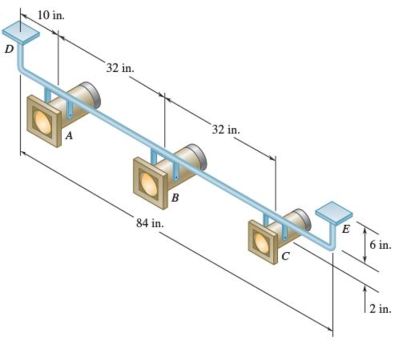
Fig. P16.85
Want to see the full answer?
Check out a sample textbook solution
Chapter 16 Solutions
Vector Mechanics for Engineers: Statics and Dynamics
Additional Engineering Textbook Solutions
Applied Statics and Strength of Materials (6th Edition)
INTERNATIONAL EDITION---Engineering Mechanics: Statics, 14th edition (SI unit)
Fundamentals Of Thermodynamics
DeGarmo's Materials and Processes in Manufacturing
Thermodynamics: An Engineering Approach
Applied Fluid Mechanics (7th Edition)


- Each paddle wheel of a steamer have a mass of 1600 kg and a radius of gyration of 1.2 meters. The steamer turns to port in a circle of 160 meters radius at 24 km/hr. The speed of the paddle is 90 rpm. Determine the magnitude and effect of the gyroscopic couple acting on the steamer.arrow_forwardAn experimental Fresnel-lens solar-energy concentrator can rotate about the horizontal axis AB that passes through its mass center G. It is supported at A and B by a steel framework that can rotate about the vertical y axis. The concentrator has a mass of 30 Mg, a radius of gyration of 12 m about its axis of symmetry CD, and a radius of gyration of 10 m about any transverse axis through G. Knowing that the angular velocities w1 and w2 have constant magnitudes equal to 0.20 rad/s and 0.25 rad/s, respectively, determine for the position 0= 60° (a) the forces exerted on the concentrator at A and B, (b)the couple M2k applied to the concentrator at that instant.arrow_forwardThe rotor of an electric motor has an angular velocity of 3600 rpm when the load and power are cut off. The 120-lb rotor, which has a centroidal radius of gyration of 9 in., then coasts to rest. Knowing that kinetic friction results in a couple of magnitude 2.5 lb·ft exerted on the rotor, determine the number of revolutions that the rotor executes before coming to rest.arrow_forward
- A slender 9-lb rod can rotate in a vertical plane about a pivot at B. A spring of constant k = 21 lb/ft and of unstretched length 6 in. is attached to the rod as shown in the figure. Knowing that the rod is released from rest in the position shown in the figure, determine its angular velocity after it has rotated through 90 degree .arrow_forwardA shaft carries four masses, B, C, and D of magnitude 200 kg, 300 kg, 400 kg, and 200 kg respectively and revolving at radii 80 mm, 70 mm, 60 mm, and 80 mm in planes measured from A at 300 mm, 400 mm and 700 mm. The angles between the cranks measured anticlockwise are A to B 45º, B to C 70º, and C to D 120º. the balancing masses are to be placed in planes X and Y. The distance between the planes A and X is 100 mm, between X and Y is 400 mm and between Y and D is 200 mm. If the balancing masses revolve at a radius of 100 mm, find their magnitude and angular positions.arrow_forwardThe steel roll shown has a mass of 1200 kg, a centroidal radius of gyration of 150 mm, and is lifted by two cables looped around its shaft. Knowing that for each cable TA = 3100 N and TB = 3300 N, determine (a) the angular acceleration of the roll, (b) the acceleration of its mass center.arrow_forward
- Two uniform cylinders, each of mass m = 6 kg and radius r = 125 mm, are connected by a belt as shown. Knowing that at the instant shown the angular velocity of cylinder A is 30 rad/s counterclockwise, determine (a) the time required for the angular velocity of cylinder A to be reduced to 5 rad/s, (b) the tension in the portion of belt connecting the two cylinders.arrow_forwardThe upper and lower ends of the arms are pivoted on the axis of the governor has equal arms of length 44cm. The extension arms of the lower links are each 10cm long and parallel to the axis.When the governor at minimum and maximum position, the radii of rotation of the balls are 17cm and 24cm respectively. The mass of each ball is 10 kg and the mass of the central load is 102 kg. Determine : 1.The range of angular speed of the governor and identify the type of governor 2.Draw the line diagram when the governor at minimum and maximum positionarrow_forwardIn the helicopter shown; a vertical tail propeller is used to pre- vent rotation of the cab as the speed of the main blades is changed. Assuming that the tail propeller is not operating determine the final angular velocity of the cab after the speed of the main blades has been changed from I80 to 240 rpm. (The speed of the main blades is measured relative to the cab, and the cab has a centroidal moment of inertia of 650 lb.ft.s2. Each of the four main blades is assumed to be a slender rod 14 ft weighing 55 lb.)arrow_forward
- A 7.5 kg disk A radius of 0.6 m initially rotating clockwise at 300 rev/min is engaged with an 8.5 kg disk B of radius 0.4 m initially rotating counter clockwise at 700 rev/min, where the moment of inertia of a disk is given as I=1/2mr^2. Determine their combined angular speed (in rpm) and direction after the meshing of the two disks.arrow_forwardThe 10-in.-radius brake drum is attached to a larger flywheel which is not shown. The total mass moment of inertia of the flywheel and drum is 22 lb ⋅ ft ⋅ s 2 and the coefficient of kinetic friction between the drum and the brake shoe is 0.41. Knowing that the initial angular velocity is 255 rpm clockwise, determine the force which must be exerted by the hydraulic cylinder at point B if the system is to stop in 85 revolutions. DO NOT ROUND OFF IN THE SOLUTION. ROUND OFF ONLY THE FINAL ANSWERarrow_forwardThe 80-mm-radius gear shown has a mass of 5 kg and a centroidal radius of gyration of 60 mm. The 4-kg rod AB is attached to the center of the gear and to a pin at B that slides freely in a vertical slot. Knowing that the system is released from rest when 0 = 60°, determine the velocity of the center of the gear when 0 = 20°.arrow_forward
 Elements Of ElectromagneticsMechanical EngineeringISBN:9780190698614Author:Sadiku, Matthew N. O.Publisher:Oxford University Press
 Mechanics of Materials (10th Edition)Mechanical EngineeringISBN:9780134319650Author:Russell C. HibbelerPublisher:PEARSON
 Thermodynamics: An Engineering ApproachMechanical EngineeringISBN:9781259822674Author:Yunus A. Cengel Dr., Michael A. BolesPublisher:McGraw-Hill Education
 Control Systems EngineeringMechanical EngineeringISBN:9781118170519Author:Norman S. NisePublisher:WILEY
 Mechanics of Materials (MindTap Course List)Mechanical EngineeringISBN:9781337093347Author:Barry J. Goodno, James M. GerePublisher:Cengage Learning
 Engineering Mechanics: StaticsMechanical EngineeringISBN:9781118807330Author:James L. Meriam, L. G. Kraige, J. N. BoltonPublisher:WILEY