
Concept explainers
Videos
The test rig shown was developed to perform fatigue testing on fitness trampolines. A motor drives the 200-mm radius flywheel AB, which is pinned at its center point A, in a counterclockwise direction with a constant angular velocity of 120 rpm. The flywheel is attached to slider CD by the 400-mm connecting rod BC. The mass of the connecting rod BC is 5 kg, and the mass of the link CD and foot is 2 kg. At the instant when θ = 0° and the foot is just above the trampoline, determine the force exerted by pin C on rod BC.
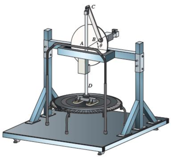
Fig. P16.127
Find the force exerted by pin C on rod BC for fitness trampoline.
Answer to Problem 16.127P
The force exerted by pin C on rod BC is
Explanation of Solution
Given information:
The radius of the flywheel AB is
The mass of the connecting rod BC is
The mass of the link CD and foot is
The length of the rod BC is
The angular velocity is
The angle is
Calculation:
Convert the unit of angular velocity from
Consider the acceleration due to gravity as
Calculate the weight
Calculate the weight of rod BC
Substitute
Calculate the weight of link CD
Substitute
Sketch the geometry of the rig as shown in Figure 1.
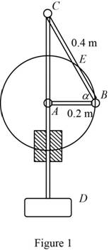
Refer to Figure 1.
Calculate the angle
Calculate the position vectors
Position of B with respect to A.
Position of C with respect to B.
Position of G with respect to B.
Calculate the moment of inertia
Substitute
Sketch the Free Body Diagram of the rod CD as shown in Figure 2.
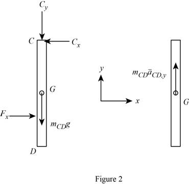
Refer to Figure 2.
Apply the Equilibrium of forces along y direction as shown below.
Substitute
Sketch the Free Body Diagram of rod BC as shown in Figure 3.
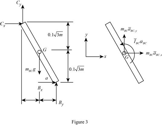
Refer to Figure 3.
Apply the Equilibrium of forces along x direction as shown below.
Substitute
Apply the Equilibrium of forces along y direction as shown below.
Substitute
Apply the Equilibrium of moment about G as shown below.
Substitute
Calculate the velocity
Substitute
Calculate the velocity
Substitute
Resolving the i and j components as shown below.
For i component.
For j component.
Substitute
Calculate the relative acceleration
Substitute
Calculate the relative acceleration
Substitute
Resolving i and j components as shown below.
For i component,
For j component,
Substitute
Calculate the relative acceleration
Substitute
Resolving i and j components as shown below.
Calculate the reaction
Substitute
Calculate the reaction
Substitute
Calculate the reaction
Substitute
Substitute
Calculate the reaction at C as shown below.
Substitute
Therefore, the force exerted by pin C on rod BC is
Want to see more full solutions like this?
Chapter 16 Solutions
Vector Mechanics for Engineers: Statics and Dynamics
Additional Engineering Textbook Solutions
Introduction To Finite Element Analysis And Design
INTERNATIONAL EDITION---Engineering Mechanics: Statics, 14th edition (SI unit)
Engineering Mechanics: Dynamics (14th Edition)
Thermodynamics: An Engineering Approach
Manufacturing Engineering & Technology
Vector Mechanics for Engineers: Statics, 11th Edition


- The rotor of an electric motor has an angular velocity of 3600 rpm when the load and power are cut off. The 120-lb rotor, which has a centroidal radius of gyration of 9 in., then coasts to rest. Knowing that kinetic friction results in a couple of magnitude 2.5 lb·ft exerted on the rotor, determine the number of revolutions that the rotor executes before coming to rest.arrow_forwardA 1200-kg satellite designed to study the sun has an angular velocity of w0 = (0.050 rad/s)i + (0.075 rad/s)k when two small jets are activated at A and B in a direction parallel to the y axis. Knowing that the coordinate axes are principal centroidal axes, that the radii of gyration of the satellite are and that each jet produces a 50-N thrust, determine (a ) the required operating time of each jet if the angular velocity of the satellite is to be reduced to zero, (b ) the resulting change in the velocity of the mass center G.arrow_forwardA slender 9-lb rod can rotate in a vertical plane about a pivot at B. A spring of constant k = 21 lb/ft and of unstretched length 6 in. is attached to the rod as shown in the figure. Knowing that the rod is released from rest in the position shown in the figure, determine its angular velocity after it has rotated through 90 degree .arrow_forward
- Disk A, of weight 5 lb and radius r = 3 in., is at rest when it is placed in contact with a belt that moves at a constant speed v = 50 ft/s. Knowing that μk = 0.20 between the disk and the belt, determine the time required for the disk to reach a constant angular velocity.arrow_forwardThe upper and lower ends of the arms are pivoted on the axis of the governor has equal arms of length 44cm. The extension arms of the lower links are each 10cm long and parallel to the axis.When the governor at minimum and maximum position, the radii of rotation of the balls are 17cm and 24cm respectively. The mass of each ball is 10 kg and the mass of the central load is 102 kg. Determine : 1.The range of angular speed of the governor and identify the type of governor 2.Draw the line diagram when the governor at minimum and maximum positionarrow_forwardThe 2-lb gear A is constrained to roll on the fixed gear B but is free to rotate about axle AD. Axle AD has a length of 20 in., a negligible weight, and is connected by a clevis to the vertical shaft DE that rotates as shown with a constant angular velocity w1. Assuming that gear A can be approximated by a thin disk with a radius of 4 in., determine the largest allowable value of w1 if gear A is not to lose contact with gear B.arrow_forward
- The 30-kg uniform disk A and the bar BC are at rest and the 5-kg uniform disk D has an initial angular velocity of w1 with a magnitude of 440 rpm when the compressed spring is released and disk D contacts disk contacts disk A. The system rotates freely about the vertical spindle BE. After a period of slippage, disk D rolls without slipping. Knowing that the magnitude of the final angular velocity of disk D is 176 rpm, determine the final angular velocities of bar BC and disk A. Neglect the mass of bar BC.arrow_forwardThe mechanism shown is one of two identical mechanisms attached to the two sides of a 200-lb uniform rectangular door. Edge ABC of the door is guided by wheels of negligible mass that roll in horizontal and vertical tracks. A spring with a constant k is attached to wheel B in such a way that its tension is zero when 0 = 30°, Knowing that the door is released from rest in the position 0 = 45° and reaches the vertical position with an angular velocity of 0.6 rad/s, determine the spring constant k.arrow_forwardIn the engine system shown l = 250 mm and b = 100 mm. The connecting rod BD is assumed to be a 1.2-kg uniform slender rod and is attached to the 1.8-kg piston P. During a test of the system, crank AB is made to rotate with a constant angular velocity of (400) rpm CW with no force applied to the face of the piston. Determine the velocity and acceleration of the piston P when θ = 90°. (Neglect the effect of the weight of the rod.)arrow_forward
 Elements Of ElectromagneticsMechanical EngineeringISBN:9780190698614Author:Sadiku, Matthew N. O.Publisher:Oxford University Press
 Mechanics of Materials (10th Edition)Mechanical EngineeringISBN:9780134319650Author:Russell C. HibbelerPublisher:PEARSON
 Thermodynamics: An Engineering ApproachMechanical EngineeringISBN:9781259822674Author:Yunus A. Cengel Dr., Michael A. BolesPublisher:McGraw-Hill Education
 Control Systems EngineeringMechanical EngineeringISBN:9781118170519Author:Norman S. NisePublisher:WILEY
 Mechanics of Materials (MindTap Course List)Mechanical EngineeringISBN:9781337093347Author:Barry J. Goodno, James M. GerePublisher:Cengage Learning
 Engineering Mechanics: StaticsMechanical EngineeringISBN:9781118807330Author:James L. Meriam, L. G. Kraige, J. N. BoltonPublisher:WILEY