
Concept explainers
Videos
Solve Prob. 16.137 when θ = 90°.
16.137 In the engine system shown, l = 250 mm and b = 100 mm. The connecting rod BD is assumed to be a 1.2-kg uniform slender rod and is attached to the 1.8-kg piston P. During a test of the system, crank AB is made to rotate with a constant angular velocity of 600 rpm clockwise with no force applied to the face of the piston. Determine the forces exerted on the connecting rod at B and D when θ = 180°. (Neglect the effect of the weight of the rod.)
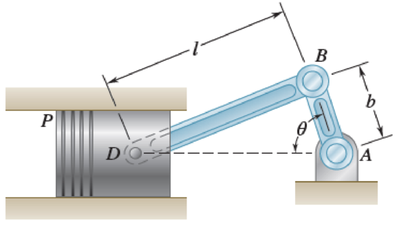
Fig. P16.137
The forces exerted on the connecting rod at B and D when
Answer to Problem 16.138P
The forces exerted on the connecting rod at B is
The forces exerted on the connecting rod at D is
Explanation of Solution
Given information:
The length of the rod BD is
The length of the rod AB is
The mass of the rod BD is
The mass of the piston P is
The angular velocity of AB is
Calculation:
Consider the acceleration due to gravity
Calculate the angular velocity in
Sketch the Free body Diagram of the system as shown in Figure 1.
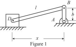
Refer to Figure 1.
Calculate the distance
Substitute
Calculate the position vectors as shown below.
Position of B with respect to A.
Position of D with respect to B.
Position of mass center G with respect to D.
Calculate the velocity at B
Substitute
Calculate the velocity at D
Substitute
Resolving the i and j components as shown below.
For j component.
For i component.
Substitute
Consider that the angular acceleration as
Calculate the acceleration at B
Substitute
Calculate the acceleration
Substitute
Resolving i and j components as shown below.
For j component.
For i component.
Substitute
Calculate the acceleration of mass center G of bar BD
Substitute
Resolving the components as shown below.
Calculate the mass moment of inertia for BD
Substitute
Sketch the Free Body Diagram of the piston with the bar BD as shown in Figure 2.
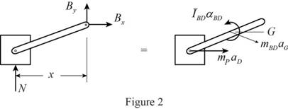
Refer to Figure 2.
Apply the Equilibrium of forces along x direction as shown below.
Substitute
Apply the Equilibrium of moment about B as shown below.
Substitute
Apply the Equilibrium of forces along y direction as shown below.
Substitute
Calculate the force acting at B as shown below.
Substitute
Hence, the forces exerted on the connecting rod at B is
Sketch the Free Body Diagram of the piston as shown in Figure 3.
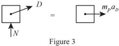
Refer to Figure 3.
Calculate the force acting on the rod at D as shown below.
Substitute
Calculate the magnitude of force at D as shown below.
Therefore, the forces exerted on the connecting rod at D is
Want to see more full solutions like this?
Chapter 16 Solutions
Vector Mechanics for Engineers: Statics and Dynamics
Additional Engineering Textbook Solutions
Fundamentals of Aerodynamics
Foundations of Materials Science and Engineering
Applied Fluid Mechanics (7th Edition)
Fluid Mechanics Fundamentals And Applications
Engineering Mechanics: Statics
Mechanics of Materials (10th Edition)


- The 10-in.-radius brake drum is attached to a larger flywheel which is not shown. The total mass moment of inertia of the flywheel and drum is 22 lb ⋅ ft ⋅ s 2 and the coefficient of kinetic friction between the drum and the brake shoe is 0.41. Knowing that the initial angular velocity is 255 rpm clockwise, determine the force which must be exerted by the hydraulic cylinder at point B if the system is to stop in 85 revolutions. determine the force which must be exerted by the hydraulic cylinder at point B if the system is to stop in 85 revolutions. DO NOT ROUND OFF IN THE SOLUTION. ROUND OFF ONLY IN 2 DECIMAL PLACE IN THE FINAL ANSWER.arrow_forwardThe shutter shown was formed by removing one quarter of a disk of 0.75-in. radius and is used to interrupt a beam of light emanating from a lens at C. Knowing that the shutter weighs 0.125 lb and rotates at the constant rate of 24 cycles per second, determine the magnitude of the force exerted by the shutter on the shaft at Aarrow_forwardThe 8-in. radius brake drum is attached to a larger flywheel that is not shown. The total mass moment of inertia of the drum and the flywheel is 15 lb.ft.s2 and the coefficient of kinetic friction between the drum and the brake shoe is 0.40. Knowing that the angular velocity of the flywheel is 450 rpm clockwise when a force P of magnitude 65 lbf. is applied to the pedal C, determine the number of the revolutions executed by the flywheel before it comes to rest. (The final answer should be in two decimal places with correct units)arrow_forward
- A wheel of radius r and centroidal radius of gyration k is released from rest on the incline shown at time t = 0. Assuming that the wheel rolls without sliding, determine (a) the velocity of its center at time t, (b) the coefficient of static friction required to prevent slipping.arrow_forwardA 1200-kg satellite designed to study the sun has an angular velocity of w0 = (0.050 rad/s)i + (0.075 rad/s)k when two small jets are activated at A and B in a direction parallel to the y axis. Knowing that the coordinate axes are principal centroidal axes, that the radii of gyration of the satellite are and that each jet produces a 50-N thrust, determine (a ) the required operating time of each jet if the angular velocity of the satellite is to be reduced to zero, (b ) the resulting change in the velocity of the mass center G.arrow_forwardA 48-kg advertising panel of length 2a = 2.4 m and width 2b = 1.6 m is kept rotating at a constant rate w1 about its horizontal axis by a small electric motor attached at A to frame ACB. This frame itself is kept rotating at a constant rate w2 about a vertical axis by a second motor attached at C to the column CD. Knowing that the panel and the frame complete a full revolution in 6 s and 12 s, respectively, express, as a function of the angle 0, the dynamic reaction exerted on column CD by its support at D.arrow_forward
- A 255-lbf block is suspended from an inextensible cable which is wrapped around a drum of 1.75-ft radius rigidly attached to a flywheel. The drum and flywheel have a combined centroidal moment of inertia 12 lb . ft . s 2 . At the instant shown, the velocity of the block is unknown directed downward. Knowing that the bearing at A is poorly lubricated and that the bearing friction is equivalent to a couple M of magnitude 65 lb .ft, determine the velocity of the block before it has moved 3.5 ft downward if at S2 speed is 13.5ft/sarrow_forwardThe 80-mm-radius gear shown has a mass of 5 kg and a centroidal radius of gyration of 60 mm. The 4-kg rod AB is attached to the center of the gear and to a pin at B that slides freely in a vertical slot. Knowing that the system is released from rest when 0 = 60°, determine the velocity of the center of the gear when 0 = 20°.arrow_forwardA long ladder of length l, mass m, and centroidal mass moment of inertia I is placed against a house at an angle 0=0O. Knowing that the ladder is released from rest, determine the angular velocity of the ladder when 0=02. Assume the ladder can slide freely on the horizontal ground and on the vertical wall.arrow_forward
- The rotor of an electric motor has an angular velocity of 3600 rpm when the load and power are cut off. The 110-lb rotor, which has a centroidal radius of gyration of 9 in., then coasts to rest. Knowing that the kinetic friction of the rotor produces a couple with a magnitude of 2.5 1b.ft determine the number of revolutions that the rotor executes before coming to rest.arrow_forwardThe rotor of an electric motor has an angular velocity of 3570 rpm when the load and power are cut off. The 65-kg rotor, which has a centroidal radius of gyration of 175mm, until it reaches the maximum speed of 5250 rpm. Knowing that the kinetic friction results in a couple of magnitude 4.5 N.m exerted on the rotor, determine the number of revolutions that the rotor executes, before achieving its maximum speed and the time it took. (The final answer should be in two decimal places with correct units)arrow_forwardA uniform 144-lb cube is attached to a uniform 136-lb circular shaft as shown, and a couple M with a constant magnitude is applied to the shaft when the system is at rest. Knowing that r = 4 in., L= 12 in., and the angular velocity of the system is 960 rpm after 4 s, determine the magnitude of the couple M.arrow_forward
 Elements Of ElectromagneticsMechanical EngineeringISBN:9780190698614Author:Sadiku, Matthew N. O.Publisher:Oxford University Press
 Mechanics of Materials (10th Edition)Mechanical EngineeringISBN:9780134319650Author:Russell C. HibbelerPublisher:PEARSON
 Thermodynamics: An Engineering ApproachMechanical EngineeringISBN:9781259822674Author:Yunus A. Cengel Dr., Michael A. BolesPublisher:McGraw-Hill Education
 Control Systems EngineeringMechanical EngineeringISBN:9781118170519Author:Norman S. NisePublisher:WILEY
 Mechanics of Materials (MindTap Course List)Mechanical EngineeringISBN:9781337093347Author:Barry J. Goodno, James M. GerePublisher:Cengage Learning
 Engineering Mechanics: StaticsMechanical EngineeringISBN:9781118807330Author:James L. Meriam, L. G. Kraige, J. N. BoltonPublisher:WILEY