
Concept explainers
Videos
Consider the spur gears shown in Figure P3.15, where
Figure P3.15 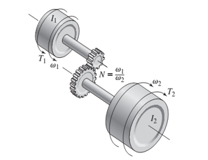
Want to see the full answer?
Check out a sample textbook solution
Chapter 3 Solutions
SYSTEM DYNAMICS CONNECT


- A hydraulic clutch of a motor car works as follows: A foot pedal with a mechanical advantage of 2,5:1 acts on the master cylinder which is 15 mm in diameter. Hydraulic fluid is displaced to the slave cylinder which is 20 mm in diameter. The force from the slave cylinder on the clutch is 850 N and the foot pedal moves 70 mm when pressed in.1.1 Determine the force which must be applied to the foot pedal.1.2 Determine the distance that the slave cylinder will move if the foot is depressed fully.arrow_forwardAn electric motor has a rotor with a mass moment of inertia of 22 ft-lb-s2. What torque is required to accelerate it from rest to 1,174 rpm in 3.6 seconds? Provide your answer in lb-ft and round to the nearest whole number. An electric motor has a rotor with a mass moment of inertia of 22 ft-lb-s2. What torque is required to accelerate it from rest to 1,174 rpm in 3.6 seconds? Provide your answer in lb-ft and round to the nearest whole number.arrow_forward1. A 10 kg, 0.5 m radius wheel rotates with an angular acceleration of 10 rad/s/s. What is the torque ( KNm ) developed at the rim of the wheel? 2. A 10 kg, 0.5 m radius wheel running at 1800 rpm develops a torque of 50 KNm. Find the power ( KW ) transmitted by the wheel. 3. The total acceleration develop at the rim of the wheel 100 m/s/s. What is the wheel centripetal acceleration ( m/s/s ) if the tangential acceleration is 80 m/s/s ? 4. A particle moves in such a way that a = 2 s + 1 m/s/s , where t is in seconds. If the particle has moved 9 m , what is the velocity ( m/s ) at that point ?arrow_forward
- For the double slider mechanism shown in the following figure, the crank OA rotates at a uniform speed of 100 rad/s CW. we need to find the required torque for the crank, if two forces act at sliders B and C as shown in the figure. (P = 2KN, Q = 1KN). OA = 30 cm, AB = AC = 100 cm. mB = mC = 1 Kg. Neglect other links weights. The velocity of slip of slider B in m/s2 = Answer 1 Choose... The velocity of slip of slider C in m/s2 = Answer 2 Choose... The acceleration of slip of slider B in m/s2 = Answer 3 Choose... The acceleration of slip of slider C in m/s2 = Answer 4 Choose... The magnitude of required torque for the crank in N.m = Answer 5 Choose...arrow_forwardConsider a disc of mass, M with radius 0.5 m on a slope with angle 45 degrees to the horizontal. It has a good grip on the slope and does not slip. The disc is constructed so that its mass per unit area, ρ(r) = r1/2 kg m−2, with r being the radial distance in metres from the axis of the disc. What is the equation describing the linear acceleration of the centre of mass of the disc down the slope in terms of the angular acceleration of the disc.arrow_forwardTwo cylinders rolling in the opposite direction has a speed ratio of 3. If the diameter of driver is 10 inches, find the center distance between cylinders. A. 15 in B. 10 in C. 25 in. D. 20 in. Please solve the Problem elaborately. Your solution will be use as reference for my studies. Thank you so much your work will be appreciated much!arrow_forward
- For the double slider mechanism shown in the following figure, the crank OA rotates at a uniform speed of 24 rad/s ccw. we need to find the required torque for the crank, if two forces act at sliders B and C as shown in the figure. (P = 4 kN, Q = 2 kN). OA = 10 cm, AB = AC = 70 cm. mg = mc = 5 Kg. Neglect other links weights. (5) (2) (3) B (4) (6) C 45° X. The velocity of slip of slider B in m/s² = Choose.. + The velocity of slip of slider C in m/s? = Choose... + The acceleration of slip of slider B in m/s² = Choose.. + The acceleration of slip of slider C in m/s² = Choose.. + The magnitude of required torque for the crank in N.m = Choose..arrow_forward1. Using Lagrangian Mechanics, find the acceleration of the double Atwood machine assuming the pulley is masslessarrow_forwardA motor is attached to a pulley of radius 10 cm and mass 1 kg. A belt passes through the pulley that connects to a hollow sphere with a radius of 40 cm and a mass of 2 kg (see figure below). If the final speed of the first round, the angular speed of the SPHERE is 3πrad/s:a) What is the final energy consumption of the motor? b) If the torque is constant, what is the magnitude of the motor's torque? that there is no friction in the axes of the sphere and that all energy consumed by the motor is transformed into work.arrow_forward
- A box of mass m = 0.7 kg is attached to a rope which is wrapped around a physical pulley with a radius of R = 10.2 cm and a rotational inertia of I = 0.075 kg·m2. When the box is released it starts to fall down with a constant acceleration and, at the same time, the pulley starts to spin up, see the picture below. Assuming that the pulley is frictionless, what is the magnitude of the box's acceleration and what is the tension in the rope? The acceleration of the box, a ? The tension in the rope, T? If the box starts from rest and traveled downwards a distance of h = 28 cm, what is the speed of the box and what is the angular velocity of the pulley? The speed of the box, v =? The angular velocity of the pulley, ω? -------------------------------------------------------------- A Merry Go Round carousel has a radius of R = 2.4 m and a rotational inertia of I = 695 kg·m2. A 75‑kg student is on the carousel at the midpoint between the carousel's center and the rim (at R/2 distance from…arrow_forwardIf a disk (radius R) is subjected to two tangential forces of equal value and accelerates initially, but then reaches a constant angular velocity how would you represent the torque acting upon the center of the desk?arrow_forwardAs seen in the figure, three masses are connected to each other with the system set up on a table. Table friction and kinetic coefficient of friction is 0.35. (g = 10m / s2). b) Find the acceleration of each mass. c) Find the tensile forces on the ropes. d) How many meters will the object of 6kg go down after t = 3s after the system is released?arrow_forward
 Elements Of ElectromagneticsMechanical EngineeringISBN:9780190698614Author:Sadiku, Matthew N. O.Publisher:Oxford University Press
 Mechanics of Materials (10th Edition)Mechanical EngineeringISBN:9780134319650Author:Russell C. HibbelerPublisher:PEARSON
 Thermodynamics: An Engineering ApproachMechanical EngineeringISBN:9781259822674Author:Yunus A. Cengel Dr., Michael A. BolesPublisher:McGraw-Hill Education
 Control Systems EngineeringMechanical EngineeringISBN:9781118170519Author:Norman S. NisePublisher:WILEY
 Mechanics of Materials (MindTap Course List)Mechanical EngineeringISBN:9781337093347Author:Barry J. Goodno, James M. GerePublisher:Cengage Learning
 Engineering Mechanics: StaticsMechanical EngineeringISBN:9781118807330Author:James L. Meriam, L. G. Kraige, J. N. BoltonPublisher:WILEY