
Concept explainers
Videos
For the geared system shown in Figure P3.23, assume that shaft inertias and the gear inertias
Figure P3.23
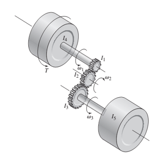
The speed ratios are
Derive the system model in terms of the speed
Want to see the full answer?
Check out a sample textbook solution
Chapter 3 Solutions
SYSTEM DYNAMICS CONNECT


- In the figure below Atwood’s machine is drawn - two masses and hanging over a massive pulley of rotational inertia and radius , connected by a massless unstretchable string. The string rolls on the pulley without slipping.a) Find the acceleration of the system and the tensions in the string on both sides of the pulley in terms of in terms of given variables.b) Why are the rope tensions on two sides of the pulley not the same? Explain it physically.c) Suppose mass and the system is released from rest with the masses at equal heights. When mass has descended a distance , find the velocity of each mass and the angular velocity of the pulley.[4***] A string is rolled around a cylinder( kg) as shown in figure. A person pulls on the string, causing the cylinder to roll without slipping along the floorarrow_forwardFor the double slider mechanism shown in the following figure, the crank OA rotates at a uniform speed of 24 rad/s ccw. we need to find the required torque for the crank, if two forces act at sliders B and C as shown in the figure. (P = 4 kN, Q = 2 kN). OA = 10 cm, AB = AC = 70 cm. mg = mc = 5 Kg. Neglect other links weights. (5) (2) (3) B (4) (6) C 45° X. The velocity of slip of slider B in m/s² = Choose.. + The velocity of slip of slider C in m/s? = Choose... + The acceleration of slip of slider B in m/s² = Choose.. + The acceleration of slip of slider C in m/s² = Choose.. + The magnitude of required torque for the crank in N.m = Choose..arrow_forwardFind the differential equations for the motion of a pendulum in that its mass m is connected to a flexible helical spring (constant of stiffness K and length l. ). Assume that the movement takes place in a vertical plane.arrow_forward
- MECHANICAL VIBRATIONS The system shown in Fig. P3.3 consists of a uniform rod which has length 1, mass m, and mass moment of inertia about its mass center 1. The rod is supported by two springs which have stiffness coefficients ky and k2, as shown in the figure. Determine the system differential equation of motion for small oscillations. Determine also the system natural frequency.arrow_forwardA spring-mass system is shown in the following figure. Use m=3.5 kg and k=100 N/m. a. Determine the static deflection δst . Insert your answer in meters correct up to at least a third decimal place. b. Determine the system period τ. Insert your answer in seconds correct up to at least a third decimal place. c. Determine the maximum velocity vmax which results if the cylinder is displaced 140mm downward from its equilibrium position and released from rest. Insert your answer in m/s correct up to at least a third decimal place.arrow_forwardConsider a disc of mass, M with radius 0.5 m on a slope with angle 45 degrees to the horizontal. It has a good grip on the slope and does not slip. The disc is constructed so that its mass per unit area, ρ(r) = r1/2 kg m−2, with r being the radial distance in metres from the axis of the disc. What is the equation describing the linear acceleration of the centre of mass of the disc down the slope in terms of the angular acceleration of the disc.arrow_forward
- A rotating mechanical system and free body diagrams for this system are given below.The torque vector denoted by number 3 in the free body diagram of J1Which of the following could it be?arrow_forwardA gyroscope is pulled with a 30 cm long string. The string is wrapped around a 2.0 mm diameter axle then pulled with a constant force of 5.0 N. Assume the spinning ring's diameter is 5.0 cm its mass is 30 g and that all of the mass is in the ring not the spokes (the ring can be modeled as a hoop). Determine the final rate at which the ring spins (in rpm). You can solve this using Newton's 2nd Law and Kinematics but it is much easier to use W = ΔK for rotational kinetic energy.arrow_forward1.A rotor has an inner radius of 10.0 cm and an outer radius of 25.0 cm. It is fixed to a frictionless axle that goes through its center. The moment of inertia (I) of the rotor is 0.0235 kg m2. A set of 5 constant forces act on the rotor, as shown in the diagram below. (a) Find the net torque acting on the rotor, in units of Nm. Be sure to give both the magnitude and direction. (b) Find the angular acceleration of the rotor, in units of rad/s2. Give both the magnitude and direction. (c) Assuming it starts from rest at t = 0, how long does it take for the rotor to reach an angular speed of 565 revolutions pre minute (rpm)? Give your answer in seconds. (d) At t = 2.50 seconds, how many complete revolutions will the rotor have made?arrow_forward
- A 54 kg skip attached to a steel rope on a crane is used to hoist bricks from the ground to the top of a construction site. The steel rope is wound onto a lifting drum with a diameter of 700 mm which rotates. The lifting drum is situated on the top floor. Calculate the torque (in N.m) on the lifting drum, to lift 20 bricks weighing 150 kg, ignoring the weight of the steel rope.arrow_forwardPART OF MECHANICAL VIBRATIONS SUBJECT USE VIRTUAL WORK The uniform bar shown in Fig. P3.6 has mass m, length l, and mass moment of inertia 1 about its mass center. The bar is supported by two springs kı and k2, as shown in the figure. Obtain the differential equation of motion and determine the natural frequency of the system in the case of small oscillations.arrow_forwardquestion 2 A mass ! hangs on the end of a cord around a pulley of radius 5 and moment of inertia 6, rotating with an angular velocity ,, as shown in the figure below. The rim of the pulley is attached to a spring (with constant 7). Assume small oscillations so that the spring remains essentially horizontal and neglect friction so that the conservation of energy of the system yields: 1 2 !91 + 1 2 6,1 + 1 2 7;1 − !); = =, ?ℎABA , = 9 5 , = = CDE&/, ; = FG&H'5CA!AE/ IBD! AJ(G'GKBG(! Find the natural circular frequency of the system in terms of !, 5, 7,6, and ).arrow_forward
 Elements Of ElectromagneticsMechanical EngineeringISBN:9780190698614Author:Sadiku, Matthew N. O.Publisher:Oxford University Press
 Mechanics of Materials (10th Edition)Mechanical EngineeringISBN:9780134319650Author:Russell C. HibbelerPublisher:PEARSON
 Thermodynamics: An Engineering ApproachMechanical EngineeringISBN:9781259822674Author:Yunus A. Cengel Dr., Michael A. BolesPublisher:McGraw-Hill Education
 Control Systems EngineeringMechanical EngineeringISBN:9781118170519Author:Norman S. NisePublisher:WILEY
 Mechanics of Materials (MindTap Course List)Mechanical EngineeringISBN:9781337093347Author:Barry J. Goodno, James M. GerePublisher:Cengage Learning
 Engineering Mechanics: StaticsMechanical EngineeringISBN:9781118807330Author:James L. Meriam, L. G. Kraige, J. N. BoltonPublisher:WILEY