
SYSTEM DYNAMICS CONNECT
3rd Edition
ISBN: 9781264201730
Author: Palm
Publisher: MCG CUSTOM
expand_more
expand_more
format_list_bulleted
Videos
Textbook Question
Chapter 3, Problem 3.9P
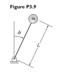
Figure P3.9 shows an inverted pendulum. Obtain the equation of motion in terms of the angle
Expert Solution & Answer
Want to see the full answer?
Check out a sample textbook solution
Students have asked these similar questions
For each of the systems shown in Figure P4.52, the input is the force f andthe outputs are the displacements x1 and x2 of the masses. The equilibriumpositions with f = 0 correspond to x1 = x2 = 0. Neglect any friction betweenthe masses and the surface. Derive the equations of motion of the systems.
A mass weighing 4 pounds is attached to a spring whose spring constant is 36 lb/ft.
Find the equation of motion.
For the mechanical system shown below, find the equation of motions and the system matrix. Where (x = X ewt)
Chapter 3 Solutions
SYSTEM DYNAMICS CONNECT
Ch. 3 - Prob. 3.1PCh. 3 - A baseball is thrown horizontally from the...Ch. 3 - For the mass shown in Figure 3.1.3b. m=10 kg, =25...Ch. 3 - A particle of mass m=19 kg slides down a...Ch. 3 - A particle of mass m slides down a frictionless...Ch. 3 - A radar tracks the flight of a projectile (see...Ch. 3 - Table 3.2.1 gives the inertia IO for a point mass...Ch. 3 - A motor supplies a moment M to the pulley of...Ch. 3 - Figure P3.9 shows an inverted pendulum. Obtain the...Ch. 3 - The two masses shown in Figure P3.10 are released...
Ch. 3 - The motor in Figure P3.11 lifts the mass mL by...Ch. 3 - Instead of using the system shown in Figure 3.2.6a...Ch. 3 - Consider the cart shown in Figure P3.13. Suppose...Ch. 3 - Consider the cart shown in Figure P3.13. Suppose...Ch. 3 - Consider the spur gears shown in Figure P3.15,...Ch. 3 - Consider the spur gears shown in Figure P3.15,...Ch. 3 - Derive the expression for the equivalent inertia...Ch. 3 - Prob. 3.18PCh. 3 - The geared system shown in Figure P3.19 represents...Ch. 3 - Prob. 3.20PCh. 3 - Prob. 3.21PCh. 3 - Prob. 3.22PCh. 3 - For the geared system shown in Figure P3.23,...Ch. 3 - For the geared system discussed in Problem 3.23,...Ch. 3 - The geared system shown in Figure P3.25 is similar...Ch. 3 - Consider the rack-and-pinion gear shown in Figure...Ch. 3 - The lead screw (also called a power screw or a...Ch. 3 - Prob. 3.29PCh. 3 - Derive the equation of motion of the block of mass...Ch. 3 - Assume the cylinder in Figure P3.31 rolls without...Ch. 3 - Prob. 3.33PCh. 3 - Prob. 3.34PCh. 3 - A slender rod 1.4 m long and of mass 20 kg is...Ch. 3 - Prob. 3.36PCh. 3 - Prob. 3.37PCh. 3 - The pendulum shown in Figure P3.38 consists of a...Ch. 3 - Prob. 3.39PCh. 3 - A single link of a robot arm is shown in Figure...Ch. 3 - 3.41 It is required to determine the maximum...Ch. 3 - Figure P3.42 illustrates a pendulum with a base...Ch. 3 - Figure P3.43 illustrates a pendulum with a base...Ch. 3 - 3.44 The overhead trolley shown in Figure P3.44 is...Ch. 3 - Prob. 3.45PCh. 3 - The “sky crane” shown on the text cover was a...
Knowledge Booster


Learn more about
Need a deep-dive on the concept behind this application? Look no further. Learn more about this topic, mechanical-engineering and related others by exploring similar questions and additional content below.Similar questions
- Five masses m1, m2, m3 m4 and m5 are 150 kg, 250 kg, 190 kg , 120 kg and 210 kg respectively. The corresponding radii of rotation are 0.2 m, 0.15 m, 0.25 m 0.1 and 0.3 m respectively and the angles between successive masses are 45°, 75° 20 and 110°. Find the position and magnitude of the balance mass required, graphically, if its radius of rotation is 0.25 marrow_forwardFigure Q1 shows a uniform plank, rests upon a horizontal bench with one end of the bar projecting over the sharp edge of the bench, the bar being at right angles to this edge. The plank is pulled out of horizontally until the centre of gravity overhangs the edge by a distance a, and is then released. The plank rotates about the edge and then slides down.arrow_forwardFigure Q3(b) shows a uniform bar AB of mass = 8 kg hinged at point C. Point A is connected to a spring to maintain the bar in vertical direction, and the stiffness k = 500 N/m. If point A is displaced counter-clockwise by a small angle θ = 3.5 degree and released, (i) With the free body diagram and kinetic diagram, determine the initial horizontal displacement of A.arrow_forward
- You construct a version of the cart and bucket, but with a slope whose angle can be adjusted. You use a cart of mass 167 kg and a bucket of mass 57.0 kg. The cable has negligible mass, and there is no friction. What must be the angle of the slope so that the cart moves downhill at a constant speed and the bucket moves upward at the same constant speed? With this choice of angle, what will be the tension in the cable?arrow_forwardYou make a conical pendulum (Figure 1) using a string of length 0.900 m and a bob of mass 0.350 kg. When the bob is moving in a circle at a constant speed, the string is at an angle of 10.0∘ from the vertical. What is the radius of the circle around which the bob moves? How much time does it take the bob to complete one circle? What is the tension in the string?arrow_forwardMECHANICAL VIBRATIONS The system shown in Fig. P3.3 consists of a uniform rod which has length 1, mass m, and mass moment of inertia about its mass center 1. The rod is supported by two springs which have stiffness coefficients ky and k2, as shown in the figure. Determine the system differential equation of motion for small oscillations. Determine also the system natural frequency.arrow_forward
- Consider the mass spring system shown in the figure below. The system is subject to a time dependent forcearrow_forwardFind the motion equations of the system shown in the figure.arrow_forwardA rock is thrown horizontally off a 100 m high-rise building as shown in Figure Q4(a). It lands 95 m away. At what speed was it thrown?arrow_forward
- Consider the system formed by three ideal springs, a rigid rod of negligible mass and a body of mass M, as illustrated in the figure. The two springs attached to the ceiling are identical and have spring constant K1 = 2 kg/s2 and natural length L1 = 10 cm, while the third has spring constant K2 = 3 kg/s2 and natural length L2 = 20 cm. Assume that the mass M and the rod oscillate only along the vertical x-axis and that the gravitational acceleration is uniform with magnitude g=10 m/s2. What is the mass oscillation period? Choose the closest value.arrow_forward3kg ball connected to horizontal AB with cable. AB rotates with constant angular velocity w about vertical axis. if angle of cable with vertical is theta= 30 degree, find angular velocity and tension of the cable.arrow_forwardQ/ Find the reaction Force of system in A,B,C Shown in figarrow_forward
arrow_back_ios
SEE MORE QUESTIONS
arrow_forward_ios
Recommended textbooks for you
 Elements Of ElectromagneticsMechanical EngineeringISBN:9780190698614Author:Sadiku, Matthew N. O.Publisher:Oxford University Press
 Mechanics of Materials (10th Edition)Mechanical EngineeringISBN:9780134319650Author:Russell C. HibbelerPublisher:PEARSON
 Thermodynamics: An Engineering ApproachMechanical EngineeringISBN:9781259822674Author:Yunus A. Cengel Dr., Michael A. BolesPublisher:McGraw-Hill Education
 Control Systems EngineeringMechanical EngineeringISBN:9781118170519Author:Norman S. NisePublisher:WILEY
 Mechanics of Materials (MindTap Course List)Mechanical EngineeringISBN:9781337093347Author:Barry J. Goodno, James M. GerePublisher:Cengage Learning
 Engineering Mechanics: StaticsMechanical EngineeringISBN:9781118807330Author:James L. Meriam, L. G. Kraige, J. N. BoltonPublisher:WILEY
Elements Of Electromagnetics
Mechanical Engineering
ISBN:9780190698614
Author:Sadiku, Matthew N. O.
Publisher:Oxford University Press
Mechanics of Materials (10th Edition)
Mechanical Engineering
ISBN:9780134319650
Author:Russell C. Hibbeler
Publisher:PEARSON
Thermodynamics: An Engineering Approach
Mechanical Engineering
ISBN:9781259822674
Author:Yunus A. Cengel Dr., Michael A. Boles
Publisher:McGraw-Hill Education
Control Systems Engineering
Mechanical Engineering
ISBN:9781118170519
Author:Norman S. Nise
Publisher:WILEY
Mechanics of Materials (MindTap Course List)
Mechanical Engineering
ISBN:9781337093347
Author:Barry J. Goodno, James M. Gere
Publisher:Cengage Learning
Engineering Mechanics: Statics
Mechanical Engineering
ISBN:9781118807330
Author:James L. Meriam, L. G. Kraige, J. N. Bolton
Publisher:WILEY
Physics 33 - Fluid Statics (1 of 10) Pressure in a Fluid; Author: Michel van Biezen;https://www.youtube.com/watch?v=mzjlAla3H1Q;License: Standard YouTube License, CC-BY