
Concept explainers
Videos
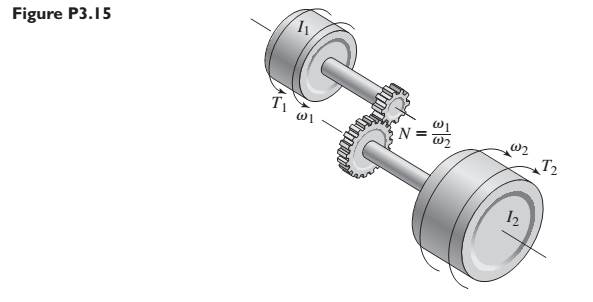
Consider the spur gears shown in Figure P3.15, where
Want to see the full answer?
Check out a sample textbook solution
Chapter 3 Solutions
SYSTEM DYNAMICS CONNECT


- An elevator weighing 2,000 lb attain an upward velocity of 16 ft/sec in 4 seconds with uniform acceleration. What is the tension in the supporting cables?arrow_forwardTwo cylinders rolling together have a speed ratio of 3:1. The center-to-center distance is 30in. Find the diameters of the cylinders if they are rotating in (a) the opposite direction, and (b) same direction.arrow_forwardIf a disk (radius R) is subjected to two tangential forces of equal value and accelerates initially, but then reaches a constant angular velocity how would you represent the torque acting upon the center of the desk?arrow_forward
- 1. The blades of a rotary lawnmower are 30cm long and rotate at 315rad/s. Find the linear speed of the blade tips and their angular speed in rpm? 2. A rotating platform is to be used to test aircraft equipment under accelerations of 6 grams. If the equipment is 50cm from the axis, what angular speed is needed?arrow_forwardThe propeller on Don Karnage's airplane can be modeled as three identical thin rods of uniform density extending radially from the rotational axis of the propeller. To take off, the propeller must accelerate from rest to 633 rpm in 4 s. If the length and mass of each rod are 0.872 m and 3.11 kg, what must be the magnitude of torque in N*m) necessary to accelerate the propeller? Explain how you solved the problem involving something undergoing angular acceleration Be sure to state what your known and unknown quantities are, what concepts were applied, and what equations were used!arrow_forwardConsider a disc of mass, M with radius 0.5 m on a slope with angle 45 degrees to the horizontal. It has a good grip on the slope and does not slip. The disc is constructed so that its mass per unit area, ρ(r) = r1/2 kg m−2, with r being the radial distance in metres from the axis of the disc. What is the equation describing the linear acceleration of the centre of mass of the disc down the slope in terms of the angular acceleration of the disc.arrow_forward
- Five masses m1, m2, m3 m4 and m5 are 150 kg, 250 kg, 190 kg , 120 kg and 210 kg respectively. The corresponding radii of rotation are 0.2 m, 0.15 m, 0.25 m 0.1 and 0.3 m respectively and the angles between successive masses are 45°, 75° 20 and 110°. Find the position and magnitude of the balance mass required, graphically, if its radius of rotation is 0.25 marrow_forwardThe system shown in the figure first starts to move without speed. Of reelsassuming that their masses and frictional effects are neglected, each blockCalculate the acceleration? (m: mass, g = 9.81 m / s2)arrow_forwardA motor is attached to a pulley of radius 10 cm and mass 1 kg. A belt passes through the pulley that connects to a hollow sphere with a radius of 40 cm and a mass of 2 kg (see figure below). If the final speed of the first round, the angular speed of the SPHERE is 3πrad/s:a) What is the final energy consumption of the motor? b) If the torque is constant, what is the magnitude of the motor's torque? that there is no friction in the axes of the sphere and that all energy consumed by the motor is transformed into work.arrow_forward
- Q6/ A car travelling at speed of 300 m/sec strikes a stone of mass 0.5 kg and 20 cm in size .Estimate Impulse of the force by the stone on the car? Q7/ A ball of mass 0.4 kg is thrown against a brick wall. When it strikes the wall it is moving horizontally to the left at 30 m/sec ,and it rebounds horizontally to the right at 20 m/sec. find the impulse of the force exerted on the wall ?arrow_forward1. A 10 kg, 0.5 m radius wheel rotates with an angular acceleration of 10 rad/s/s. What is the torque ( KNm ) developed at the rim of the wheel? 2. A 10 kg, 0.5 m radius wheel running at 1800 rpm develops a torque of 50 KNm. Find the power ( KW ) transmitted by the wheel. 3. The total acceleration develop at the rim of the wheel 100 m/s/s. What is the wheel centripetal acceleration ( m/s/s ) if the tangential acceleration is 80 m/s/s ? 4. A particle moves in such a way that a = 2 s + 1 m/s/s , where t is in seconds. If the particle has moved 9 m , what is the velocity ( m/s ) at that point ?arrow_forwardExample 9.15 A rope, to which a weight is attached, passes around a pulley 50 cm in diameter. The angular acceleration of the pulley is 18 rad/s2. If the pulley is initially rest, find a- The time required for the weight to attain a velocity of 15 m/s b- The number of revolution through which the pulley rotates during that period, c- The total acceleration of a point on the rim of the pulley 0.5 second after it was at rest.arrow_forward
 Elements Of ElectromagneticsMechanical EngineeringISBN:9780190698614Author:Sadiku, Matthew N. O.Publisher:Oxford University Press
 Mechanics of Materials (10th Edition)Mechanical EngineeringISBN:9780134319650Author:Russell C. HibbelerPublisher:PEARSON
 Thermodynamics: An Engineering ApproachMechanical EngineeringISBN:9781259822674Author:Yunus A. Cengel Dr., Michael A. BolesPublisher:McGraw-Hill Education
 Control Systems EngineeringMechanical EngineeringISBN:9781118170519Author:Norman S. NisePublisher:WILEY
 Mechanics of Materials (MindTap Course List)Mechanical EngineeringISBN:9781337093347Author:Barry J. Goodno, James M. GerePublisher:Cengage Learning
 Engineering Mechanics: StaticsMechanical EngineeringISBN:9781118807330Author:James L. Meriam, L. G. Kraige, J. N. BoltonPublisher:WILEY