
Videos
(a)
Equation of motion of the roller in terms of its rotational velocity,
Answer to Problem 3.33P
Explanation of Solution
Given:
Roller radius = R
Inertia of roller =
Mass of roller =
Weight of roller = 800N
Diameter of roller = 0.4m
The roller does not slip.
Concept used:
The motion of this object is defined by its translational motion in the plane and its rotational motion about an axis perpendicular to the plane. Two force equations describe the translational motion, and a moment equation is needed to describe the rotational motion.
For an objects’ planar motion which rotates only about an axis perpendicular to the plane, the equation of motion can be written down using Newton’s Second Law.
Equation of Motion:
Where
Using Newton’s laws for plane motion,
Where,
Derivation of Equation of motion:
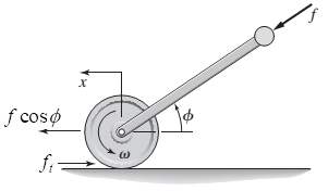
Free body diagram of the roller:

Equations describing the translational motion in the x -direction:
The acceleration,
v is the translational velocity.
Equation describing the rotational motion:
Substitute
Assuming the roller does not slip,
Substituting this in
Inertia of roller,
Substituting inertia in equation
Substituting the values
Conclusion:
Equation of motion of the roller in terms of its rotational velocity,
(b)
Equation of motion of the roller in terms of its displacement,
Answer to Problem 3.33P
Explanation of Solution
Given:
Roller radius = R
Inertia of roller =
Mass of roller =
Weight of roller = 800N
Diameter of roller = 0.4m
The roller does not slip.
Concept used:
The motion of this object is defined by its translational motion in the plane and its rotational motion about an axis perpendicular to the plane. Two force equations describe the translational motion, and a moment equation is needed to describe the rotational motion.
For an objects’ planar motion which rotates only about an axis perpendicular to the plane, the equation of motion can be written down using Newton’s Second Law.
Equation of Motion:
Where
Using Newton’s laws for plane motion,
Where,
Derivation of Equation of motion:
Free body diagram of the roller:
Equations describing the translational motion in the x -direction:
The acceleration,
v is the translational velocity.
Equation describing the rotational motion:
Substitute
Assuming the roller does not slip,
Substituting this in
Inertia of roller,
Substituting inertia in equation
Substituting the values
Conclusion:
Equation of motion of the roller in terms of its rotational velocity,
Want to see more full solutions like this?
Chapter 3 Solutions
SYSTEM DYNAMICS CONNECT


 Elements Of ElectromagneticsMechanical EngineeringISBN:9780190698614Author:Sadiku, Matthew N. O.Publisher:Oxford University Press
 Mechanics of Materials (10th Edition)Mechanical EngineeringISBN:9780134319650Author:Russell C. HibbelerPublisher:PEARSON
 Thermodynamics: An Engineering ApproachMechanical EngineeringISBN:9781259822674Author:Yunus A. Cengel Dr., Michael A. BolesPublisher:McGraw-Hill Education
 Control Systems EngineeringMechanical EngineeringISBN:9781118170519Author:Norman S. NisePublisher:WILEY
 Mechanics of Materials (MindTap Course List)Mechanical EngineeringISBN:9781337093347Author:Barry J. Goodno, James M. GerePublisher:Cengage Learning
 Engineering Mechanics: StaticsMechanical EngineeringISBN:9781118807330Author:James L. Meriam, L. G. Kraige, J. N. BoltonPublisher:WILEY