
Videos
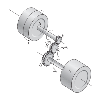
For the geared system discussed in Problem 3.23, shown in Figure P3.23, the inertias are given in
The speed ratios are
Derive the system model in terms of the speed
Figure P3.23
The speed ratios are
Derive the system model in terms of the speed
Want to see the full answer?
Check out a sample textbook solution
Chapter 3 Solutions
SYSTEM DYNAMICS LL+CONNECT


- 1.A rotor has an inner radius of 10.0 cm and an outer radius of 25.0 cm. It is fixed to a frictionless axle that goes through its center. The moment of inertia (I) of the rotor is 0.0235 kg m2. A set of 5 constant forces act on the rotor, as shown in the diagram below. (a) Find the net torque acting on the rotor, in units of Nm. Be sure to give both the magnitude and direction. (b) Find the angular acceleration of the rotor, in units of rad/s2. Give both the magnitude and direction. (c) Assuming it starts from rest at t = 0, how long does it take for the rotor to reach an angular speed of 565 revolutions pre minute (rpm)? Give your answer in seconds. (d) At t = 2.50 seconds, how many complete revolutions will the rotor have made?arrow_forwardA 100 ft cable weighing 5 lb / ft supports a safe weighing 500 lb. Find the work done in winding 80 ft of the cable on a drum.arrow_forwardA rotating mechanical system and free body diagrams for this system are given below.The torque vector denoted by number 3 in the free body diagram of J1Which of the following could it be?arrow_forward
- Consider a disc of mass, M with radius 0.5 m on a slope with angle 45 degrees to the horizontal. It has a good grip on the slope and does not slip. The disc is constructed so that its mass per unit area, ρ(r) = r1/2 kg m−2, with r being the radial distance in metres from the axis of the disc. What is the equation describing the linear acceleration of the centre of mass of the disc down the slope in terms of the angular acceleration of the disc.arrow_forwardSTATICS OF RIGID BODIES FORCE VECTORS POSITION VECTORSarrow_forwardAn electric elevator with a motor at the top has a multistrand cable weighing 8.4 lb/ft. When the car is on the first floor 270 feet of cable are paid out, and effectively 0 feet when the car is on the top floor. How much work does the motor do to lift an 1800 lb car and cable from the first floor to the top? Provide a picture model, give the approximate equation, then solve.arrow_forward
- A mass weighing 4 pounds is attached to a spring whose spring constant is 36 lb/ft. Find the equation of motion.arrow_forwardA motor drives four loads, two have rotational motion and two have translational motion. The momentof inertia of the motor is 1.2kg-m^2. The motor runs at a speed of 1000rpm. The table below shows thedetails of the four loads. Calculate the power developed by the motor. (Load ;Type of Motion; Speed; Inertia / Mass; Torque / Force) 1; Rotational; 200 rpm; 7 kg-m^2; 10 N-m 2; Rotational; 200 rpm; 5 kg-m^2; 6 N-m 3; Translational; 10 m/s; 10 kg; 20 N4; Translational; 10 m/s; 20 kg; 30 Narrow_forwardAn electric motor is accelerating a 250 kg load with acceleration of 1.2 m/s? througha gear box as shown Figure Q1(b). The rope that carries the load and spiral spring are encircled on a pulley with diameter 1.2m. Gear box ratio is 0. 1 and gear box efficiency is 100%, while gear box equivalent moment inertia is 5.55 km?. Neglect friction effect in this drive system and assume spiral spring force is X newtonCalculate the torque of the motor needed to bring up the load with acceleration1.2 m/s?.arrow_forward
- A crankline mechanism like these below, if it is known that O2A length is 5 cm, ab length is 10 centimeters and p = 100 newtons look for the forces that are occurring in the mechanism and the torque on link 2.arrow_forwardIn the figure below Atwood’s machine is drawn - two masses and hanging over a massive pulley of rotational inertia and radius , connected by a massless unstretchable string. The string rolls on the pulley without slipping.a) Find the acceleration of the system and the tensions in the string on both sides of the pulley in terms of in terms of given variables.b) Why are the rope tensions on two sides of the pulley not the same? Explain it physically.c) Suppose mass and the system is released from rest with the masses at equal heights. When mass has descended a distance , find the velocity of each mass and the angular velocity of the pulley.[4***] A string is rolled around a cylinder( kg) as shown in figure. A person pulls on the string, causing the cylinder to roll without slipping along the floorarrow_forwardThus subject is Statics of Rigid Bodies. Show your solutionarrow_forward
 Elements Of ElectromagneticsMechanical EngineeringISBN:9780190698614Author:Sadiku, Matthew N. O.Publisher:Oxford University Press
 Mechanics of Materials (10th Edition)Mechanical EngineeringISBN:9780134319650Author:Russell C. HibbelerPublisher:PEARSON
 Thermodynamics: An Engineering ApproachMechanical EngineeringISBN:9781259822674Author:Yunus A. Cengel Dr., Michael A. BolesPublisher:McGraw-Hill Education
 Control Systems EngineeringMechanical EngineeringISBN:9781118170519Author:Norman S. NisePublisher:WILEY
 Mechanics of Materials (MindTap Course List)Mechanical EngineeringISBN:9781337093347Author:Barry J. Goodno, James M. GerePublisher:Cengage Learning
 Engineering Mechanics: StaticsMechanical EngineeringISBN:9781118807330Author:James L. Meriam, L. G. Kraige, J. N. BoltonPublisher:WILEY