
Videos
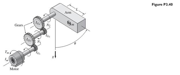
A single link of a robot arm is shown in Figure P3.40. The arm mass is m and its center of mass is located a distance L from the joint, which is driven by a motor torque
The values for the link are
Want to see the full answer?
Check out a sample textbook solution
Chapter 3 Solutions
SYSTEM DYNAMICS LL+CONNECT


- 'A model for the elbow joint models the bicep muscle connecting to the horizontal forearm by a vertical tendon 4cm from the elbow joint. A mass m is held in the hand 30cm from the elbow joint. If the maximum tension that can be exerted by the tendon before injury occurs is 2250N, find the maximum mass that can be held in this way.' Im stuck on this questionarrow_forwardDuring a bicep curl on a bicep curl machine, I'm curling a weight stack of 100 pounds (single arm...I'm jacked like that). At this very moment, the weight stack has a moment arm of 0.12m, my elbow has an angle of 63deg, my muscle force vector has an angle of 23deg, and it attaches 3cm below my elbow joint on my radius. How much force must my bicep create right at this moment to hold the weight stack in place?arrow_forwardFor the double slider mechanism shown in the following figure, the crank OA rotates at a uniform speed of 100 rad/s CW. we need to find the required torque for the crank, if two forces act at sliders B and C as shown in the figure. (P = 2KN, Q = 1KN). OA = 30 cm, AB = AC = 100 cm. mB = mC = 1 Kg. Neglect other links weights. The velocity of slip of slider B in m/s2 = Answer 1 Choose... The velocity of slip of slider C in m/s2 = Answer 2 Choose... The acceleration of slip of slider B in m/s2 = Answer 3 Choose... The acceleration of slip of slider C in m/s2 = Answer 4 Choose... The magnitude of required torque for the crank in N.m = Answer 5 Choose...arrow_forward
- Find the differential equations for the motion of a pendulum in that its mass m is connected to a flexible helical spring (constant of stiffness K and length l. ). Assume that the movement takes place in a vertical plane.arrow_forwardTake the mass of the block is M(kilogram=Newton-second2/meter), the spring constant is K(Newton/meter), the coefficient of viscous friction is fv(Newton-second/meter), distance takenin time is x(t)(meter) and force used in the system is f(t)(Newton). Write the transfer functionsfor figure 1.1, and figure 1.2.Solve only this--> Accept that the M=2 kg, K=1 N/m, fv=1 N-s/m and find the transfer function according to thosevalues.arrow_forwardA rotating mechanical system and free body diagrams for this system are given below.The torque vector denoted by number 3 in the free body diagram of J1Which of the following could it be?arrow_forward
- show your solution how you get the solutionsubject:Dynamics of Rigid bodiesarrow_forwardSuppose an automobile engine can produce 195 N⋅m of torque, and assume this car is suspended so that the wheels can turn freely. Each wheel acts like a 14 kg disk that has a 0.195 m radius. The tires act like 2.15-kg rings that have inside radii of 0.18 m and outside radii of 0.34 m. The tread of each tire acts like a 8.5-kg hoop of radius 0.335 m. The 16-kg axle acts like a solid cylinder that has a 1.75-cm radius. The 29.5-kg drive shaft acts like a solid cylinder that has a 3.25-cm radius. Calculate the angular acceleration, in radians per squared second, produced by the motor if 95.0% of this torque is applied to the drive shaft, axle, and rear wheels of a car.arrow_forwardhow many degrees of freedom in this system and how do they arise?arrow_forward
- The schematic diagram of a large cannon is shown in Fig. 2.31. When the gun is fired, high pressure gases accelerate the projectile inside the barrel to a very high velocity. The reaction force pushes the gun barrel in the direction opposite that of the projectile. Since it is desirable to bring the gun barrel to rest in the shortest time without oscillation, it is made to translate backward against a critically damped spring-damper system called the recoil mechanism. In a particular case, the gun barrel and the recoil mechanism have a mass of 500 kg with a recoil spring of stiffness 10,000 N/m. The gun recoils 0.4 m upon firing. Find (1) the critical damping coefficient of the damper, (2) the initial recoil velocity of the gun, and (3) the time taken by the gun to return to a position 0.1 m from its initial position.arrow_forwardIf a disk (radius R) is subjected to two tangential forces of equal value and accelerates initially, but then reaches a constant angular velocity how would you represent the torque acting upon the center of the desk?arrow_forward(system dynamics and control) q2 is given in image q3) ?arrow_forward
 Automotive Technology: A Systems Approach (MindTa...Mechanical EngineeringISBN:9781133612315Author:Jack Erjavec, Rob ThompsonPublisher:Cengage Learning