
Concept explainers
Videos
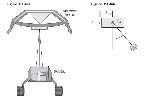
The “sky crane” shown on the text cover was a novel solution to the problem of landing the 2000 lb Curiosity rover on the surface of Mars. Curiosity hangs from the descent stage by 60-foot-long nylon tethers (Figure P3.46a). The descent stage uses its thrusters to hover as the rover is lowered to the surface. Thus the rover behaves like a pendulum whose base is moving, just like the pendulum analyzed in Problem 3.42 (see Figure P3.42). However, problem 3.42 neglected the mass of the base, but the descent stage also has significant mass. So a better model is the one shown in Figure P3.46b. The rover mass is
Derive the equations of motion of the system in terms of the angle
Want to see the full answer?
Check out a sample textbook solution
Chapter 3 Solutions
SYSTEM DYNAMICS LL+CONNECT


- Figure Q1 shows a uniform plank, rests upon a horizontal bench with one end of the bar projecting over the sharp edge of the bench, the bar being at right angles to this edge. The plank is pulled out of horizontally until the centre of gravity overhangs the edge by a distance a, and is then released. The plank rotates about the edge and then slides down.arrow_forwardA uniform ladder 8 meters long and weighing 350 N rest against a smooth vertical wall at an angle of 30 to the wall. A 700-N man stands 6 meters up from the bottom of the ladder. Find the horizontal force necessary at the base to keep the ladder from slipping Show the Figure/FBD, given and the formula usedarrow_forwardThe man in the figure below is pulling a drum over a circular hill. All surfaces are smooth (no friction forces). If the drum weighs 60N, what is the tension on the rope for the drum position shown?arrow_forward
- Question If you used an ideal pulley of the type shown in picture (a) to support a car engine of mass 145 kg , (a) What would be the tension in the rope? (b) What force must the ceiling supply, assuming you pull straight down on the rope? The pulleys system mass is 5.50 kgarrow_forwarda uniform ladder 8 meters long and weighing 350 N rest against a smooth vertical wall at an angle of 30° to the wall. A 700-N man stands 6 meters up from the bottom of the ladder. Find the horizontal force necessary at the base to keep the ladder from slipping. note: please show free body diagramarrow_forwardIn a closed subway car, a girl holds a helium-filled balloon by a string. While the car is traveling at constant velocity, the string of the balloon is exactly vertical. (Hint: For constant velocity, a buoyant force acts upward, but for constant deceleration, the buoyant force becomes tilted, but remains antiparallel to the tension.)a) While the subway car is braking, will the string be inclined forward or backward relative to the car? b) Suppose that the string is inclined at an angle of 20° with the vertical and remains there. What is the acceleration of the car?arrow_forward
- A uniform ladder 8 meters long and weighing 350 N rest against a smooth vertical wall at an angle of 30° to the wall. A 700-N man stands 6 meters up from the bottom of the ladder. Find the horizontal force necessary at the base to keep the ladder from slipping. please use the end at the top as the reference point.arrow_forwardA boy who weighs 98lb is playing basketball on an outdoor basketball goal that uses weights set on its base to stay upright. If the boy hangs on the edge of the rim as shows, what is the minimum number of disk weights (20lb each), that must be placed on the base at point C to keep the goal from tipping over? NOTE: If the goal is unbalanced it will tip at point A.arrow_forwardDraw the free body diagram for this problem: The boom of the wall crane 4m long is held at right angles to the wall by a wire that is attached to the wall 3m above the foot of the boom. If the load lifted is 45000N, find the tension in the wire and the compression force in the boom. Neglect the weight of the boom.arrow_forward
- A rectangular gate (6m x 4m) is e hinged at A and supported by a stopper as shown. Find the reaction Lé at the hinge neglecting the weight of the gatearrow_forwardA father lifts his child as shown in the figure below. How much torque does the child exert, taking the knee as the pivot? How much torque does the weight of the leg itself exert? What force () should the upper leg muscle exert to lift the child at a constant speed?arrow_forwardA uniform 80.0 N ladder 4.0 m long is placed against a frictionless wall with its base situated 2.0 m from the wall. Find the forces exerted by the wall and by the ground on the ladder.arrow_forward
 Elements Of ElectromagneticsMechanical EngineeringISBN:9780190698614Author:Sadiku, Matthew N. O.Publisher:Oxford University Press
 Mechanics of Materials (10th Edition)Mechanical EngineeringISBN:9780134319650Author:Russell C. HibbelerPublisher:PEARSON
 Thermodynamics: An Engineering ApproachMechanical EngineeringISBN:9781259822674Author:Yunus A. Cengel Dr., Michael A. BolesPublisher:McGraw-Hill Education
 Control Systems EngineeringMechanical EngineeringISBN:9781118170519Author:Norman S. NisePublisher:WILEY
 Mechanics of Materials (MindTap Course List)Mechanical EngineeringISBN:9781337093347Author:Barry J. Goodno, James M. GerePublisher:Cengage Learning
 Engineering Mechanics: StaticsMechanical EngineeringISBN:9781118807330Author:James L. Meriam, L. G. Kraige, J. N. BoltonPublisher:WILEY