
SYSTEM DYNAMICS LL+CONNECT
3rd Edition
ISBN: 9781264201891
Author: Palm
Publisher: MCG CUSTOM
expand_more
expand_more
format_list_bulleted
Concept explainers
Videos
Textbook Question
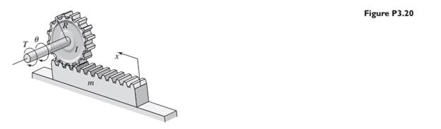
Chapter 3, Problem 3.26P
Consider the rack-and-pinion gear shown in Figure P3.20. Use the free-body diagram method to obtain the expression for the acceleration
Expert Solution & Answer
Want to see the full answer?
Check out a sample textbook solution
Students have asked these similar questions
A rock is thrown horizontally off a 100 m high-rise building as shown
in Figure Q4(a). It lands 95 m away. At what speed was it thrown?
1. A massless spring (k=400) is pulled by 25cm from its natural length and then released,the spring is attached to a 0.40kg block and oscillates across a horizontal frictionlesssurface. Calculatea. Max velocityb. Max accelerationc. Velocity, restoring force and acceleration at 20 cm from its natural length.
An electric motor is accelerating a 250 kg load with acceleration of 1.2 m/s? througha gear box as shown Figure Q1(b). The rope that carries the load and spiral spring are encircled on a pulley with diameter 1.2m. Gear box ratio is 0. 1 and gear box efficiency is 100%, while gear box equivalent moment inertia is 5.55 km?. Neglect friction effect in this drive system and assume spiral spring force is X newtonCalculate the torque of the motor needed to bring up the load with acceleration1.2 m/s?.
Chapter 3 Solutions
SYSTEM DYNAMICS LL+CONNECT
Ch. 3 - Prob. 3.1PCh. 3 - A baseball is thrown horizontally from the...Ch. 3 - For the mass shown in Figure 3.1.3b. m=10 kg, =25...Ch. 3 - A particle of mass m=19 kg slides down a...Ch. 3 - A particle of mass m slides down a frictionless...Ch. 3 - A radar tracks the flight of a projectile (see...Ch. 3 - Table 3.2.1 gives the inertia IO for a point mass...Ch. 3 - A motor supplies a moment M to the pulley of...Ch. 3 - Figure P3.9 shows an inverted pendulum. Obtain the...Ch. 3 - The two masses shown in Figure P3.10 are released...
Ch. 3 - The motor in Figure P3.11 lifts the mass mL by...Ch. 3 - Instead of using the system shown in Figure 3.2.6a...Ch. 3 - Consider the cart shown in Figure P3.13. Suppose...Ch. 3 - Consider the cart shown in Figure P3.13. Suppose...Ch. 3 - Consider the spur gears shown in Figure P3.15,...Ch. 3 - Consider the spur gears shown in Figure P3.15,...Ch. 3 - Derive the expression for the equivalent inertia...Ch. 3 - Prob. 3.18PCh. 3 - The geared system shown in Figure P3.19 represents...Ch. 3 - Prob. 3.20PCh. 3 - Prob. 3.21PCh. 3 - Prob. 3.22PCh. 3 - For the geared system shown in Figure P3.23,...Ch. 3 - For the geared system discussed in Problem 3.23,...Ch. 3 - The geared system shown in Figure P3.25 is similar...Ch. 3 - Consider the rack-and-pinion gear shown in Figure...Ch. 3 - The lead screw (also called a power screw or a...Ch. 3 - Prob. 3.29PCh. 3 - Derive the equation of motion of the block of mass...Ch. 3 - Assume the cylinder in Figure P3.31 rolls without...Ch. 3 - Prob. 3.33PCh. 3 - Prob. 3.34PCh. 3 - A slender rod 1.4 m long and of mass 20 kg is...Ch. 3 - Prob. 3.36PCh. 3 - Prob. 3.37PCh. 3 - The pendulum shown in Figure P3.38 consists of a...Ch. 3 - Prob. 3.39PCh. 3 - A single link of a robot arm is shown in Figure...Ch. 3 - 3.41 It is required to determine the maximum...Ch. 3 - Figure P3.42 illustrates a pendulum with a base...Ch. 3 - Figure P3.43 illustrates a pendulum with a base...Ch. 3 - 3.44 The overhead trolley shown in Figure P3.44 is...Ch. 3 - Prob. 3.45PCh. 3 - The “sky crane” shown on the text cover was a...
Knowledge Booster


Learn more about
Need a deep-dive on the concept behind this application? Look no further. Learn more about this topic, mechanical-engineering and related others by exploring similar questions and additional content below.Similar questions
- As seen in the figure, three masses are connected to each other with the system set up on a table. Table friction and kinetic coefficient of friction is 0.35. (g = 10m / s2). b) Find the acceleration of each mass. c) Find the tensile forces on the ropes. d) How many meters will the object of 6kg go down after t = 3s after the system is released?arrow_forwardQ6/ A car travelling at speed of 300 m/sec strikes a stone of mass 0.5 kg and 20 cm in size .Estimate Impulse of the force by the stone on the car? Q7/ A ball of mass 0.4 kg is thrown against a brick wall. When it strikes the wall it is moving horizontally to the left at 30 m/sec ,and it rebounds horizontally to the right at 20 m/sec. find the impulse of the force exerted on the wall ?arrow_forwardFive masses m1, m2, m3 m4 and m5 are 150 kg, 250 kg, 190 kg , 120 kg and 210 kg respectively. The corresponding radii of rotation are 0.2 m, 0.15 m, 0.25 m 0.1 and 0.3 m respectively and the angles between successive masses are 45°, 75° 20 and 110°. Find the position and magnitude of the balance mass required, graphically, if its radius of rotation is 0.25 marrow_forward
- A point charge q1 = +5.00 micro Coulomb is held fixed in space. From a horizontal distance of 6.00 cm, a small sphere with mass 4.00 x 10⁻³ kg and charge q2 = +2.00 micro Coulomb is fired toward the fixed charge with an initial speed of 40.0 m/s. Gravity can be neglected. What is the acceleration (in m/s2) of the sphere at the instant when its speed is 25.0 m/s?arrow_forwardFor the double slider mechanism shown in the following figure, the crank OA rotates at a uniform speed of 100 rad/s CW. we need to find the required torque for the crank, if two forces act at sliders B and C as shown in the figure. (P = 2KN, Q = 1KN). OA = 30 cm, AB = AC = 100 cm. mB = mC = 1 Kg. Neglect other links weights. The velocity of slip of slider B in m/s2 = Answer 1 Choose... The velocity of slip of slider C in m/s2 = Answer 2 Choose... The acceleration of slip of slider B in m/s2 = Answer 3 Choose... The acceleration of slip of slider C in m/s2 = Answer 4 Choose... The magnitude of required torque for the crank in N.m = Answer 5 Choose...arrow_forwardThe propeller on Don Karnage's airplane can be modeled as three identical thin rods of uniform density extending radially from the rotational axis of the propeller. To take off, the propeller must accelerate from rest to 633 rpm in 4 s. If the length and mass of each rod are 0.872 m and 3.11 kg, what must be the magnitude of torque in N*m) necessary to accelerate the propeller? Explain how you solved the problem involving something undergoing angular acceleration Be sure to state what your known and unknown quantities are, what concepts were applied, and what equations were used!arrow_forward
- You are using a lightweight rope to pull a sled along level ground. The sled weighs 435 N, the coefficient of kinetic friction between the sled and the ground is 0.200, the rope is at an angle of 12∘ above the horizontal, and you pull on the rope with a force of 115 N. Find the normal force that the ground exerts on the sled. Find the acceleration of the sled. Is the sled speeding up or slowing down?arrow_forwardThe system shown in the figure first starts to move without speed. Of reelsassuming that their masses and frictional effects are neglected, each blockCalculate the acceleration? (m: mass, g = 9.81 m / s2)arrow_forwardA simple pendulum of length L is set to oscillate in simple harmonic motion. The bob gravitational potential energy is zero at its lowest vertical point. When the bob's height is at half its maximum, h = hmax/2, then its velocity is:arrow_forward
- Four masses m1, m2, m3 and m4 are 100 kg, 200 kg, 140 kg and 160 kg respectively. The corresponding radii of rotation are 0.2 m, 0.15 m, 0.25 m and 0.3 m respectively and the angles between successive masses are 30°, 75° and 100°. Find the position and magnitude of the balance mass required, graphically, if its radius of rotation is 0.2 m.arrow_forwardA paper airplane is thrown horizontally with a velocity of 18 m/s. The plane is in the air for 7.43 s before coming to stand still on the ground. (Suppose, the planes fly horizontally without losing any altitude.) Calculate the acceleration of the plane?arrow_forwardQ2/ For the system shown below, use Newton's method to find the system matrix [M],and [K]arrow_forward
arrow_back_ios
SEE MORE QUESTIONS
arrow_forward_ios
Recommended textbooks for you
 Elements Of ElectromagneticsMechanical EngineeringISBN:9780190698614Author:Sadiku, Matthew N. O.Publisher:Oxford University Press
 Mechanics of Materials (10th Edition)Mechanical EngineeringISBN:9780134319650Author:Russell C. HibbelerPublisher:PEARSON
 Thermodynamics: An Engineering ApproachMechanical EngineeringISBN:9781259822674Author:Yunus A. Cengel Dr., Michael A. BolesPublisher:McGraw-Hill Education
 Control Systems EngineeringMechanical EngineeringISBN:9781118170519Author:Norman S. NisePublisher:WILEY
 Mechanics of Materials (MindTap Course List)Mechanical EngineeringISBN:9781337093347Author:Barry J. Goodno, James M. GerePublisher:Cengage Learning
 Engineering Mechanics: StaticsMechanical EngineeringISBN:9781118807330Author:James L. Meriam, L. G. Kraige, J. N. BoltonPublisher:WILEY
Elements Of Electromagnetics
Mechanical Engineering
ISBN:9780190698614
Author:Sadiku, Matthew N. O.
Publisher:Oxford University Press
Mechanics of Materials (10th Edition)
Mechanical Engineering
ISBN:9780134319650
Author:Russell C. Hibbeler
Publisher:PEARSON
Thermodynamics: An Engineering Approach
Mechanical Engineering
ISBN:9781259822674
Author:Yunus A. Cengel Dr., Michael A. Boles
Publisher:McGraw-Hill Education
Control Systems Engineering
Mechanical Engineering
ISBN:9781118170519
Author:Norman S. Nise
Publisher:WILEY
Mechanics of Materials (MindTap Course List)
Mechanical Engineering
ISBN:9781337093347
Author:Barry J. Goodno, James M. Gere
Publisher:Cengage Learning
Engineering Mechanics: Statics
Mechanical Engineering
ISBN:9781118807330
Author:James L. Meriam, L. G. Kraige, J. N. Bolton
Publisher:WILEY
Dynamics - Lesson 1: Introduction and Constant Acceleration Equations; Author: Jeff Hanson;https://www.youtube.com/watch?v=7aMiZ3b0Ieg;License: Standard YouTube License, CC-BY