
SYSTEM DYNAMICS LL+CONNECT
3rd Edition
ISBN: 9781264201891
Author: Palm
Publisher: MCG CUSTOM
expand_more
expand_more
format_list_bulleted
Concept explainers
Videos
Textbook Question
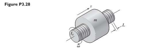
Chapter 3, Problem 3.28P
The lead screw (also called a power screw or a jack screw) is used to convert the rotation of a motor shaft into a translational motion of the mass m (see Figure P3.28). For one revolution of the screw, the mass translates a distance L (called the screw lead). As felt on the motor shaft, the translating mass appears as an equivalent inertia. Use kinetic energy equivalence to derive an expression for the equivalent inertia. Let
Expert Solution & Answer
Want to see the full answer?
Check out a sample textbook solution
Students have asked these similar questions
A mass weighing 4 pounds is attached to a spring whose spring constant is 36 lb/ft.
Find the equation of motion.
MECHANICAL VIBRATIONS
The system shown in Fig. P3.3 consists of a uniform rod which has length 1, mass m, and mass moment of inertia about its mass center 1. The rod is supported by two springs which have stiffness coefficients ky and k2, as shown in the figure. Determine the system differential equation of motion for small oscillations. Determine also the system natural frequency.
A circular solid disc of uniform thickness 20 mm, radius 200 mm and 20 kg, is used as a flywheel If it rotates at 600 rpm, what is the kinetic energy of the flywheel.
Chapter 3 Solutions
SYSTEM DYNAMICS LL+CONNECT
Ch. 3 - Prob. 3.1PCh. 3 - A baseball is thrown horizontally from the...Ch. 3 - For the mass shown in Figure 3.1.3b. m=10 kg, =25...Ch. 3 - A particle of mass m=19 kg slides down a...Ch. 3 - A particle of mass m slides down a frictionless...Ch. 3 - A radar tracks the flight of a projectile (see...Ch. 3 - Table 3.2.1 gives the inertia IO for a point mass...Ch. 3 - A motor supplies a moment M to the pulley of...Ch. 3 - Figure P3.9 shows an inverted pendulum. Obtain the...Ch. 3 - The two masses shown in Figure P3.10 are released...
Ch. 3 - The motor in Figure P3.11 lifts the mass mL by...Ch. 3 - Instead of using the system shown in Figure 3.2.6a...Ch. 3 - Consider the cart shown in Figure P3.13. Suppose...Ch. 3 - Consider the cart shown in Figure P3.13. Suppose...Ch. 3 - Consider the spur gears shown in Figure P3.15,...Ch. 3 - Consider the spur gears shown in Figure P3.15,...Ch. 3 - Derive the expression for the equivalent inertia...Ch. 3 - Prob. 3.18PCh. 3 - The geared system shown in Figure P3.19 represents...Ch. 3 - Prob. 3.20PCh. 3 - Prob. 3.21PCh. 3 - Prob. 3.22PCh. 3 - For the geared system shown in Figure P3.23,...Ch. 3 - For the geared system discussed in Problem 3.23,...Ch. 3 - The geared system shown in Figure P3.25 is similar...Ch. 3 - Consider the rack-and-pinion gear shown in Figure...Ch. 3 - The lead screw (also called a power screw or a...Ch. 3 - Prob. 3.29PCh. 3 - Derive the equation of motion of the block of mass...Ch. 3 - Assume the cylinder in Figure P3.31 rolls without...Ch. 3 - Prob. 3.33PCh. 3 - Prob. 3.34PCh. 3 - A slender rod 1.4 m long and of mass 20 kg is...Ch. 3 - Prob. 3.36PCh. 3 - Prob. 3.37PCh. 3 - The pendulum shown in Figure P3.38 consists of a...Ch. 3 - Prob. 3.39PCh. 3 - A single link of a robot arm is shown in Figure...Ch. 3 - 3.41 It is required to determine the maximum...Ch. 3 - Figure P3.42 illustrates a pendulum with a base...Ch. 3 - Figure P3.43 illustrates a pendulum with a base...Ch. 3 - 3.44 The overhead trolley shown in Figure P3.44 is...Ch. 3 - Prob. 3.45PCh. 3 - The “sky crane” shown on the text cover was a...
Knowledge Booster


Learn more about
Need a deep-dive on the concept behind this application? Look no further. Learn more about this topic, mechanical-engineering and related others by exploring similar questions and additional content below.Similar questions
- Five masses m1, m2, m3 m4 and m5 are 150 kg, 250 kg, 190 kg , 120 kg and 210 kg respectively. The corresponding radii of rotation are 0.2 m, 0.15 m, 0.25 m 0.1 and 0.3 m respectively and the angles between successive masses are 45°, 75° 20 and 110°. Find the position and magnitude of the balance mass required, graphically, if its radius of rotation is 0.25 marrow_forwardYou pull on a crate using a rope as image, except the rope is at an angle of 20.0 ∘ above the horizontal. The weight of the crate is 325 N, and the coefficient of kinetic friction between the crate and the floor is 0.230. What must be the tension in the rope to make the crate move at a constant velocity? What is the normal force that the floor exerts on the crate?arrow_forwardQ2/ For the system shown below, use Newton's method to find the system matrix [M],and [K]arrow_forward
- 'A model for the elbow joint models the bicep muscle connecting to the horizontal forearm by a vertical tendon 4cm from the elbow joint. A mass m is held in the hand 30cm from the elbow joint. If the maximum tension that can be exerted by the tendon before injury occurs is 2250N, find the maximum mass that can be held in this way.' Im stuck on this questionarrow_forwardA turntable is a uniform disc of mass 2 kg and radius 1.3 x 10⁻¹ m. The turntable is spinning at a constant rate of = 0.5 . The motor is turned off and the turntable slows to a stop in 8.0 s with constant angular deceleration. Find the (a) moment of inertia of the turntable; (b) initial rotational kinetic energy; (c) angular deceleration of the turntable while it is slowing down; (d) total angle in radians that the turntable spins while slowing down; and (e) magnitude of the frictional torque.arrow_forwardFor the mechanical system shown below, find the equation of motions and the system matrix. Where (x = X ewt)arrow_forward
- You are using a lightweight rope to pull a sled along level ground. The sled weighs 435 N, the coefficient of kinetic friction between the sled and the ground is 0.200, the rope is at an angle of 12∘ above the horizontal, and you pull on the rope with a force of 115 N. Find the normal force that the ground exerts on the sled. Find the acceleration of the sled. Is the sled speeding up or slowing down?arrow_forwardDuring a bicep curl on a bicep curl machine, I'm curling a weight stack of 100 pounds (single arm...I'm jacked like that). At this very moment, the weight stack has a moment arm of 0.12m, my elbow has an angle of 63deg, my muscle force vector has an angle of 23deg, and it attaches 3cm below my elbow joint on my radius. How much force must my bicep create right at this moment to hold the weight stack in place?arrow_forwardQ6/ A car travelling at speed of 300 m/sec strikes a stone of mass 0.5 kg and 20 cm in size .Estimate Impulse of the force by the stone on the car? Q7/ A ball of mass 0.4 kg is thrown against a brick wall. When it strikes the wall it is moving horizontally to the left at 30 m/sec ,and it rebounds horizontally to the right at 20 m/sec. find the impulse of the force exerted on the wall ?arrow_forward
- Find the equations of motion of the system using the law of conservation of energy.arrow_forwardAn elevator weighing 2,000 lb attain an upward velocity of 16 ft/sec in 4 seconds with uniform acceleration. What is the tension in the supporting cables?arrow_forwardFind the differential equations for the motion of a pendulum in that its mass m is connected to a flexible helical spring (constant of stiffness K and length l. ). Assume that the movement takes place in a vertical plane.arrow_forward
arrow_back_ios
SEE MORE QUESTIONS
arrow_forward_ios
Recommended textbooks for you
 Principles of Heat Transfer (Activate Learning wi...Mechanical EngineeringISBN:9781305387102Author:Kreith, Frank; Manglik, Raj M.Publisher:Cengage Learning
Principles of Heat Transfer (Activate Learning wi...
Mechanical Engineering
ISBN:9781305387102
Author:Kreith, Frank; Manglik, Raj M.
Publisher:Cengage Learning
Dynamics - Lesson 1: Introduction and Constant Acceleration Equations; Author: Jeff Hanson;https://www.youtube.com/watch?v=7aMiZ3b0Ieg;License: Standard YouTube License, CC-BY