
SYSTEM DYNAMICS LL+CONNECT
3rd Edition
ISBN: 9781264201891
Author: Palm
Publisher: MCG CUSTOM
expand_more
expand_more
format_list_bulleted
Concept explainers
Videos
Textbook Question
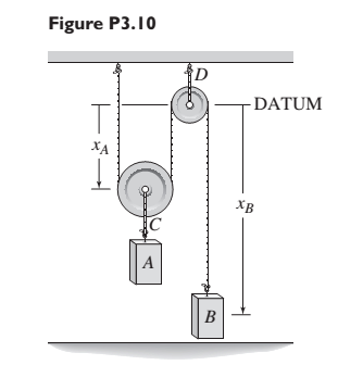
Chapter 3, Problem 3.10P
The two masses shown in Figure P3.10 are released from rest. The mass of block A is 100 kg; the mass of block B is 20kg. Ignore the masses of the pulleys and rope. Determine the acceleration of block A and of block B. Dc they rise or fall?
Expert Solution & Answer
Want to see the full answer?
Check out a sample textbook solution
Students have asked these similar questions
As seen in the figure, three masses are connected to each other with the system set up on a table. Table friction and kinetic coefficient of friction is 0.35. (g = 10m / s2).
b) Find the acceleration of each mass. c) Find the tensile forces on the ropes. d) How many meters will the object of 6kg go down after t = 3s after the system is released?
Q6/ A car travelling at speed of 300 m/sec strikes a stone of mass 0.5 kg and 20 cm in size .Estimate Impulse of the force by the stone on the car? Q7/ A ball of mass 0.4 kg is thrown against a brick wall. When it strikes the wall it is moving horizontally to the left at 30 m/sec ,and it rebounds horizontally to the right at 20 m/sec. find the impulse of the force exerted on the wall ?
Zorch, an archenemy of Superman, decides to slow Earth’s rotation to once per 29 h by exerting a force parallel to the equator, opposing the rotation. Superman is not immediately concerned, because he knows Zorch can only exert a force of 4.15 × 10⁷ N. For the purposes calculations in this problem you should treat the Earth as a sphere of uniform density even though it isn't.
a. How long, in seconds, must Zorch push with this force to accomplish his goal? (This period gives Superman time to devote to other villains.)
Chapter 3 Solutions
SYSTEM DYNAMICS LL+CONNECT
Ch. 3 - Prob. 3.1PCh. 3 - A baseball is thrown horizontally from the...Ch. 3 - For the mass shown in Figure 3.1.3b. m=10 kg, =25...Ch. 3 - A particle of mass m=19 kg slides down a...Ch. 3 - A particle of mass m slides down a frictionless...Ch. 3 - A radar tracks the flight of a projectile (see...Ch. 3 - Table 3.2.1 gives the inertia IO for a point mass...Ch. 3 - A motor supplies a moment M to the pulley of...Ch. 3 - Figure P3.9 shows an inverted pendulum. Obtain the...Ch. 3 - The two masses shown in Figure P3.10 are released...
Ch. 3 - The motor in Figure P3.11 lifts the mass mL by...Ch. 3 - Instead of using the system shown in Figure 3.2.6a...Ch. 3 - Consider the cart shown in Figure P3.13. Suppose...Ch. 3 - Consider the cart shown in Figure P3.13. Suppose...Ch. 3 - Consider the spur gears shown in Figure P3.15,...Ch. 3 - Consider the spur gears shown in Figure P3.15,...Ch. 3 - Derive the expression for the equivalent inertia...Ch. 3 - Prob. 3.18PCh. 3 - The geared system shown in Figure P3.19 represents...Ch. 3 - Prob. 3.20PCh. 3 - Prob. 3.21PCh. 3 - Prob. 3.22PCh. 3 - For the geared system shown in Figure P3.23,...Ch. 3 - For the geared system discussed in Problem 3.23,...Ch. 3 - The geared system shown in Figure P3.25 is similar...Ch. 3 - Consider the rack-and-pinion gear shown in Figure...Ch. 3 - The lead screw (also called a power screw or a...Ch. 3 - Prob. 3.29PCh. 3 - Derive the equation of motion of the block of mass...Ch. 3 - Assume the cylinder in Figure P3.31 rolls without...Ch. 3 - Prob. 3.33PCh. 3 - Prob. 3.34PCh. 3 - A slender rod 1.4 m long and of mass 20 kg is...Ch. 3 - Prob. 3.36PCh. 3 - Prob. 3.37PCh. 3 - The pendulum shown in Figure P3.38 consists of a...Ch. 3 - Prob. 3.39PCh. 3 - A single link of a robot arm is shown in Figure...Ch. 3 - 3.41 It is required to determine the maximum...Ch. 3 - Figure P3.42 illustrates a pendulum with a base...Ch. 3 - Figure P3.43 illustrates a pendulum with a base...Ch. 3 - 3.44 The overhead trolley shown in Figure P3.44 is...Ch. 3 - Prob. 3.45PCh. 3 - The “sky crane” shown on the text cover was a...
Knowledge Booster


Learn more about
Need a deep-dive on the concept behind this application? Look no further. Learn more about this topic, mechanical-engineering and related others by exploring similar questions and additional content below.Similar questions
- A rock is thrown horizontally off a 100 m high-rise building as shown in Figure Q4(a). It lands 95 m away. At what speed was it thrown?arrow_forwardA child is pulling two red wagons, with the second one tied to the first by a (non-stretching) rope. Each wagon has a mass of 10 kg. If the child exerts a force of 30 N for 5.0 m, how much has the kinetic energy of the two-wagon system changed?arrow_forwardAn elevator weighing 2,000 lb attain an upward velocity of 16 ft/sec in 4 seconds with uniform acceleration. What is the tension in the supporting cables?arrow_forward
- 4. A concrete weight of 125 kg is released from standstill and a log of mass 200 kg is moved along an inclined area of 30° to the horizontal.When the concrete weight is moved down 5 m, find that 1. What is the speed of the log? 2. What is the movement time of the concrete drum?arrow_forward1. Using Lagrangian Mechanics, find the acceleration of the double Atwood machine assuming the pulley is masslessarrow_forwardQ7/ A ball of mass 0.4 kg is thrown against a brick wall. When it strikes the wall it is moving horizontally to the left at 30 m/sec ,and it rebounds horizontally to the right at 20 m/sec. find the impulse of the force exerted on the wall ?arrow_forward
- An inextensible massless string goes over a frictionless pulley. Two weights of 100 N and 200 N are attached to the two ends of the string. The weights are released from rest, and start moving due to gravity. What is the tension in the string?arrow_forward. To promote their new album, Black Pink decided to launch a satellite into orbit that will intercept all airwaves and play their songs worldwide. To do this, he needs to mount a 200 [kg] satellite onto an 850 [kg] rocket. It blasts off vertically from a launchpad with a constant net upward acceleration of 3.80 [m/s2]. When it has reached a height of 680 [m], the satellite was released, and the rocket blew up shortly after, due to a system failure. Assume that the satellite was not damaged after the explosion. (a) What is the maximum height that the satellite will reach above the launchpad? (b) How much time will elapse after system failure before the satellite comes crashing down the launch pad? (c) How fast will the satellite be moving just before it crashes?arrow_forwardA free hanging system of 5 kg weight, and 6 kg weight, tied together with a 4 kg rope is pulled upwards with a force of 300 N. A) what is the acceleration of the system? B) what is the tension of the system? C) what is the tension from the middle of the rope ?arrow_forward
- What impulse does the force shown FIGURE exert on a 250 g particle?arrow_forwardYou are using a lightweight rope to pull a sled along level ground. The sled weighs 435 N, the coefficient of kinetic friction between the sled and the ground is 0.200, the rope is at an angle of 12∘ above the horizontal, and you pull on the rope with a force of 115 N. Find the normal force that the ground exerts on the sled. Find the acceleration of the sled. Is the sled speeding up or slowing down?arrow_forwardThe diagram shows two blocks, one 3 kg and the other 9 kg, hanging connected to the same string that passes over an ideal pulley. What acceleration do the blocks have when released from rest?arrow_forward
arrow_back_ios
SEE MORE QUESTIONS
arrow_forward_ios
Recommended textbooks for you
 Elements Of ElectromagneticsMechanical EngineeringISBN:9780190698614Author:Sadiku, Matthew N. O.Publisher:Oxford University Press
 Mechanics of Materials (10th Edition)Mechanical EngineeringISBN:9780134319650Author:Russell C. HibbelerPublisher:PEARSON
 Thermodynamics: An Engineering ApproachMechanical EngineeringISBN:9781259822674Author:Yunus A. Cengel Dr., Michael A. BolesPublisher:McGraw-Hill Education
 Control Systems EngineeringMechanical EngineeringISBN:9781118170519Author:Norman S. NisePublisher:WILEY
 Mechanics of Materials (MindTap Course List)Mechanical EngineeringISBN:9781337093347Author:Barry J. Goodno, James M. GerePublisher:Cengage Learning
 Engineering Mechanics: StaticsMechanical EngineeringISBN:9781118807330Author:James L. Meriam, L. G. Kraige, J. N. BoltonPublisher:WILEY
Elements Of Electromagnetics
Mechanical Engineering
ISBN:9780190698614
Author:Sadiku, Matthew N. O.
Publisher:Oxford University Press
Mechanics of Materials (10th Edition)
Mechanical Engineering
ISBN:9780134319650
Author:Russell C. Hibbeler
Publisher:PEARSON
Thermodynamics: An Engineering Approach
Mechanical Engineering
ISBN:9781259822674
Author:Yunus A. Cengel Dr., Michael A. Boles
Publisher:McGraw-Hill Education
Control Systems Engineering
Mechanical Engineering
ISBN:9781118170519
Author:Norman S. Nise
Publisher:WILEY
Mechanics of Materials (MindTap Course List)
Mechanical Engineering
ISBN:9781337093347
Author:Barry J. Goodno, James M. Gere
Publisher:Cengage Learning
Engineering Mechanics: Statics
Mechanical Engineering
ISBN:9781118807330
Author:James L. Meriam, L. G. Kraige, J. N. Bolton
Publisher:WILEY
Dynamics - Lesson 1: Introduction and Constant Acceleration Equations; Author: Jeff Hanson;https://www.youtube.com/watch?v=7aMiZ3b0Ieg;License: Standard YouTube License, CC-BY