Concept explainers
Videos
Our pipelined design is a bit unrealistic in that we have two write ports for the register file, but only the popq instruction requires two simultaneous writes to the register file. The other instructions could therefore use a single write port, sharing this for writing valE and valM. The following figure shows a.modified version of the write-back logic, in which we merge the write-back register IDs (W_dstE and W_dstM) into a single signal W_dstE and the write-back values (W_valE and W_yalM) into a single signal w_valE:
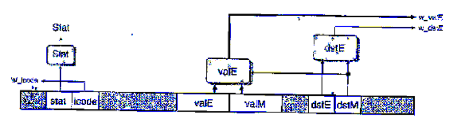
The logic for performing the merges is written in HCL as follows:
## Set E port register ID
word w_datE = [
## writing from valM
W_dstH != RNONE : W_dstM;
1: W_dstE;
};
# Set E port value
word w_valE - [
W_dstM != RNONE : W_valM;
1 : W_valE;
};
The control for these multiplexors is determined by dstE—when it indicates there is some register, then it selects the value for port E, and otherwise it selects the value for port M.
In the simulation model, we can then disable register port M, as shown by the following HCL code:
## Disable register port M
## Set M port register ID
word w_dstM = RNONE;
## Set M port value
word w_valM = 0;
The challenge then becomes to devise a way to handle popq. One method is to use the control logic to dynamically process the instruction popq rA so that it has the same effect as the two-instruction sequence
iaddq $8, %rsp
mrmovq -8 (%rsp) , rA
(See Practice Problem 4.3 for a description of the iaddq instruction.) Note the ordering of the two instructions to make sure popq %rsp works properly. You can do this by having the logic in the decode stage treat popq the same as it would the iaddq listed above, exceptthat it predicts the next PC to be equal to the current PC. On the next cycle, the popq instruction is refetched, but the instruction code is converted to a special value IPOP2. This is treated as a special instruction that has the same behavior as the mrmovq instruction listed above.
The file pipe-lw. hcl contains the modified write port logic described above. It contains a declaration of the constant IPOP2 having hexadecimal value E. It also contains the definition of a signal f_icode that generates the (code field for pipeline register D. This definition can be modified to insert the instruction code IPOP2 the second time the popq instruction is fetched. The 1-ICL file also contains a declaration of the signal f_pc, the value of the program counter generated in the fetch stage by the block labeled "Select PC" (Figure 4.57).
Modify the control logic in this the to process popq instructions in the manner we have described. See the lab material for directions on how to generate a simulator for your solution and how to test it.
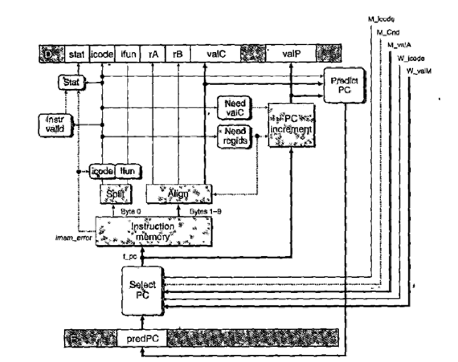
Figure 4.57 PIPE PC selection and fetch logic. Within the one cycle time limit, the processor can only predict the address of the next instruction.
Want to see the full answer?
Check out a sample textbook solution
Chapter 4 Solutions
Computer Systems: Program... -Access
Additional Engineering Textbook Solutions
Starting Out with C++: Early Objects (9th Edition)
Computer Science: An Overview (13th Edition) (What's New in Computer Science)
Web Development and Design Foundations with HTML5 (9th Edition) (What's New in Computer Science)
Starting Out With Visual Basic (7th Edition)
C Programming Language
Starting Out with Java: From Control Structures through Objects (6th Edition)


- In this setup, data for each instruction is obtained independently of how data for other instructions is obtained. When we need a(n): A Instructions/Data Sets That Vary B A Variety of Information and Directions in a C Format Exclusive Information Straight D Incident Several Insts From a Single Infusionarrow_forwardGiven the data path of the LC-3, give a complete description of the STR instruction, as outlined in the following questions STR R5, R4, #-28 1.) assemble the instruction to its binary representation, and give your answer in hexadecimal. 2.)Give the RT (Register Transfer) description of the instruction. 3.) List, in the correct sequence, every control signal set by the FSM to implement this instruction.arrow_forwardhe automation of a light is designed by interfacing it with the output port having the address 01H of 8085 microprocessor unit (MPU). For this purpose, with the help of assembly language program load the bit pattern 91 H, in register-B and 87H in register-C of MPU. Mask all the bits except D, from registers B and C. If bit Do at logic 1 in both registers, turn on the light connected to D. position of the output port 01H; otherwise, turn off the light.arrow_forward
- The automation of a light is designed by interfacing it with the output port having the address 01H of 8085 microprocessor unit (MPU). For this purpose, with the help of assembly language program load the bit pattern 91H, in register-B and 87H, in register-C of MPU. Mask all the bits except D, from registers B and C. If bit D, at lagic 1 in both registers, tum on the light connected to D, position of the output port 01H, otherwise, turn off the light.arrow_forwardWrite HCL code for the signal D_stall in the PIPE implementation.Pipeline register D must be set to bubble for a mispredicted branch ora ret instruction. As the analysis in the preceding section shows,however, it should not inject a bubble when there is a load/use hazardin combination with a ret instruction:bool D_bubble =# Mispredicted branch (E_icode == IJXX && !e_Cnd) ||# Stalling at fetch while ret passes through pipeline# but not condition for a load/use hazard!(E_icode in { IMRMOVQ, IPOPQ } && E_dstM in { d_srcA,d_srcB }) && IRET in { D_icode, E_icode, M_icode };arrow_forwardWhat would happen if an instruction was disobeyed, and why would that be the case? In the following scenarios, a TLB that is maintained by software is more efficient than one that is handled by hardware:arrow_forward
- You are given snapshots of the MIPS pipeline from two successive cycles. For each figure, fill in all the relevant information in each stage, corresponding to the instruction in that stage at that cycle. Remember to specify clearly how control signals are set. Assume $x contains x * 100 (e.g. $1 contains 100). MIPS instructions used: add rd, rs, rt rd = rs + rt or rd, rs, rt rd = rs or rt lw rt, I(rs) rt = Mem[rs + I] (load word) sw rt, I(rs) Mem[rs + I] = rt (store word)arrow_forwardFor the following assembly code that is vaguely MIPS-like, trace itsexecution in both the R3000 and R4000 pipelines using a Gantt chart (ortable of some kind).LOAD R1, Memory(12340)LOAD R2, Memory(12350)ADD R3, R1, R2 // R3 = R1 + R2ADD R3, R3, R3 // R3 = R3 + R3STORE R3, Memory(12360)arrow_forwardFor the instruction add $t0, $s0, $s1, what is the range(s) of values for $s1 that would result in overflow?arrow_forward
- Using graphical representation to show the forwarding technique cannot completely avoid the data hazard. How many stall cycles are there when the forwarding technique is used? What is the advantage of having the source register fields in a fixed location for each instruction in instruction pipeline design?arrow_forwardRead the Assembly program carefully, understand its working/functionality and answer the below given question. MOV DX, 0090 MOV DS, DX MOV BX, 0010 MOV SI, 0020 MOV AL,00 MOV DL, [SI] MOV CX, 000AP1: CMP DL, [BX] JNZ P2 ;JNZ is Jump if ZF=0 in the result of CMP instruction INC ALP2: INC BX INC SI DEC CX MOV DL, [SI] CMP CX, 0 JA P1 MOV [0030], AL INT E0090:0010 DB B8, 6F, 23, D0, 99, C5, 89, 9D, 1A, 810090:0020 DB 37, 6F, 32, B6, 11, C5, 98, 2B, 7A, C0 a. What will be displayed on the LCD after the execution of program?arrow_forwardThe problems below refer to the following sequence of instructions, and assume that it is executed on a 5-stage pipelined data-path: add $t5, $t2, $t1lw $t3, 4($t5)lw $t2, 0($t2)or $t3, $t5, $t3sw $t3, 0($t5) -------------------------------------------------------------------------------------- Identify the instruction type for the sequence of instructions. Identify the dependencies in the sequence of instructions.arrow_forward
 Database System ConceptsComputer ScienceISBN:9780078022159Author:Abraham Silberschatz Professor, Henry F. Korth, S. SudarshanPublisher:McGraw-Hill Education
 Starting Out with Python (4th Edition)Computer ScienceISBN:9780134444321Author:Tony GaddisPublisher:PEARSON
 Digital Fundamentals (11th Edition)Computer ScienceISBN:9780132737968Author:Thomas L. FloydPublisher:PEARSON
 C How to Program (8th Edition)Computer ScienceISBN:9780133976892Author:Paul J. Deitel, Harvey DeitelPublisher:PEARSON
 Database Systems: Design, Implementation, & Manag...Computer ScienceISBN:9781337627900Author:Carlos Coronel, Steven MorrisPublisher:Cengage Learning
 Programmable Logic ControllersComputer ScienceISBN:9780073373843Author:Frank D. PetruzellaPublisher:McGraw-Hill Education