
Mechanics of Materials, 7th Edition
7th Edition
ISBN: 9780073398235
Author: Ferdinand P. Beer, E. Russell Johnston Jr., John T. DeWolf, David F. Mazurek
Publisher: McGraw-Hill Education
expand_more
expand_more
format_list_bulleted
Concept explainers
Videos
Textbook Question
Chapter 4.6, Problem 73P
4.73 and 4.74 A beam of the cross section shown is made of a steel that is assumed to be elastoplastic with E = 200 GPa and σY = 240 MPa. For bending about the z-axis, determine the bending moment at which (a) yield first occurs, (b) the plastic zones at the top and bottom of the bar are 30 mm thick.
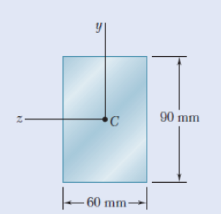
Fig. P4.74
Expert Solution & Answer
Want to see the full answer?
Check out a sample textbook solution
Students have asked these similar questions
A timber beam AB of length L and rectangular cross section carries a single concentrated load P at its midpoint C. (a) Show that the ratio Tm/ m of the maximum values of the shearing and normal stresses in the beam is equal to h/2L, where h and L are, respectively, the depth and the length of the beam. (b) Determine the depth h and the width b of the beam, knowing that L = 2 m, P = 40 kN, 7m = 960 kPa, and om = 12 MPa.
Five metal strips, each of 0.5 * 1.5-in. cross section, are bonded together to form the composite beam shown. The modulus of elasticity is 30* 106 psi for the steel, 15 *106 psi for the brass, 10 *106 psi for the aluminum. Knowing that the beam is bent about a horizontal axis by a couple of moment 12 kip·in., determine (a) the maximum stress in each of the three metals, (b) the radius of curvature of the composite beam.
A cable AB of span L and a simple beam A'B' of the same span are subjected to identical vertical loadings as shown. Show that the magnitude of the bending moment at a point C' in the beam is equal to the product T0h, where T0 is the magnitude of the horizontal component of the tension force in the cable and h is the vertical distance between point C and the chord joining the points of support A and B.
Chapter 4 Solutions
Mechanics of Materials, 7th Edition
Ch. 4.3 - 4.1 and 4.2 Knowing that the couple shown acts in...Ch. 4.3 - 4.1 and 4.2 Knowing that the couple shown acts in...Ch. 4.3 - Using an allowable stress of 155 MPa, determine...Ch. 4.3 - Solve Prob. 4.3, assuming that the wide-flange...Ch. 4.3 - Using an allowable stress of 16 ksi, determine the...Ch. 4.3 - Knowing that the couple shown acts in a vertical...Ch. 4.3 - 4.7 and 4.8 Two W4 13 rolled sections are welded...Ch. 4.3 - 4.7 and 4.8 Two W4 13 rolled sections are welded...Ch. 4.3 - 4.9 through 4.11 Two vertical forces are applied...Ch. 4.3 - 4.9 through 4.11 Two vertical forces are applied...
Ch. 4.3 - 4.9 through 4.11 Two vertical forces are applied...Ch. 4.3 - Knowing that a beam of the cross section shown is...Ch. 4.3 - Knowing that a beam of the cross section shown is...Ch. 4.3 - Solve Prob. 4.13, assuming that the beam is bent...Ch. 4.3 - Knowing that for the extruded beam shown the...Ch. 4.3 - The beam shown is made of a nylon for which the...Ch. 4.3 - Solve Prob. 4.16, assuming that d = 40 mm.Ch. 4.3 - Knowing that for the beam shown the allowable...Ch. 4.3 - 4.19 and 4.20 Knowing that for the extruded beam...Ch. 4.3 - 4.19 and 4.20 Knowing that for the extruded beam...Ch. 4.3 - Straight rods of 6-mm diameter and 30-m length are...Ch. 4.3 - A 900-mm strip of steel is bent into a full circle...Ch. 4.3 - Straight rods of 0.30-in. diameter and 200-ft...Ch. 4.3 - A 60-Nm couple is applied to the steel bar shown,...Ch. 4.3 - (a) Using an allowable stress of 120 MPa,...Ch. 4.3 - A thick-walled pipe is bent about a horizontal...Ch. 4.3 - A couple M will be applied to a beam of...Ch. 4.3 - A portion of a square bar is removed by milling,...Ch. 4.3 - In Prob. 4.28, determine (a) the value of h for...Ch. 4.3 - For the bar and loading of Concept Application...Ch. 4.3 - Prob. 31PCh. 4.3 - It was assumed in Sec. 4.1B that the normal...Ch. 4.5 - 4.33 and 4.34 A bar having the cross section shown...Ch. 4.5 - 4.33 and 4.34 A bar having the cross section shown...Ch. 4.5 - 4.35 and 4.36 For the composite bar indicated,...Ch. 4.5 - Prob. 36PCh. 4.5 - 4.37 and 4.38 Wooden beams and steel plates are...Ch. 4.5 - 4.37 and 4.38 Wooden beams and steel plates are...Ch. 4.5 - 4.39 and 4.40 A copper strip (Ec = 105 GPa) and an...Ch. 4.5 - 4.39 and 4.40 A copper strip (Ec = 105 GPa) and an...Ch. 4.5 - 4.41 and 4.42 The 6 12-in. timber beam has been...Ch. 4.5 - 4.41 and 4.42 The 6 12-in. timber beam has been...Ch. 4.5 - 4.43 and 4.44 For the composite beam indicated,...Ch. 4.5 - Prob. 44PCh. 4.5 - Prob. 45PCh. 4.5 - Prob. 46PCh. 4.5 - A concrete slab is reinforced by 58-in.-diameter...Ch. 4.5 - Solve Prob. 4.47, assuming that the spacing of the...Ch. 4.5 - The reinforced concrete beam shown is subjected to...Ch. 4.5 - Prob. 50PCh. 4.5 - Knowing that the bending moment in the reinforced...Ch. 4.5 - A concrete beam is reinforced by three steel rods...Ch. 4.5 - The design of a reinforced concrete beam is said...Ch. 4.5 - For the concrete beam shown, the modulus of...Ch. 4.5 - 4.55 and 4.56 Five metal strips, each 0.5 1.5-in....Ch. 4.5 - 4.55 and 4.56 Five metal strips, each 0.5 1.5-in....Ch. 4.5 - The composite beam shown is formed by bonding...Ch. 4.5 - A steel pipe and an aluminum pipe are securely...Ch. 4.5 - The rectangular beam shown is made of a plastic...Ch. 4.5 - Prob. 60PCh. 4.5 - Knowing that M = 250 Nm, determine the maximum...Ch. 4.5 - Knowing that the allowable stress for the beam...Ch. 4.5 - Semicircular grooves of radius r must be milled as...Ch. 4.5 - Prob. 64PCh. 4.5 - A couple of moment M = 2 kNm is to be applied to...Ch. 4.5 - The allowable stress used in the design of a steel...Ch. 4.6 - The prismatic bar shown is made of a steel that is...Ch. 4.6 - Prob. 68PCh. 4.6 - Prob. 69PCh. 4.6 - Prob. 70PCh. 4.6 - The prismatic rod shown is made of a steel that is...Ch. 4.6 - Solve Prob. 4.71, assuming that the couples M and...Ch. 4.6 - 4.73 and 4.74 A beam of the cross section shown is...Ch. 4.6 - 4.73 and 4.74 A beam of the cross section shown is...Ch. 4.6 - 4.75 and 4.76 A beam of the cross section shown is...Ch. 4.6 - Prob. 76PCh. 4.6 - 4.77 through 4.80 For the beam indicated,...Ch. 4.6 - Prob. 78PCh. 4.6 - Prob. 79PCh. 4.6 - 4.77 through 4.80 For the beam indicated,...Ch. 4.6 - 4.81 through 4.83 Determine the plastic moment Mp...Ch. 4.6 - Prob. 82PCh. 4.6 - Prob. 83PCh. 4.6 - Determine the plastic moment Mp of a steel beam of...Ch. 4.6 - Determine the plastic moment Mp of the cross...Ch. 4.6 - Determine the plastic moment Mp of a steel beam of...Ch. 4.6 - Prob. 87PCh. 4.6 - Prob. 88PCh. 4.6 - Prob. 89PCh. 4.6 - Prob. 90PCh. 4.6 - Prob. 91PCh. 4.6 - Prob. 92PCh. 4.6 - Prob. 93PCh. 4.6 - Prob. 94PCh. 4.6 - Prob. 95PCh. 4.6 - Prob. 96PCh. 4.6 - Prob. 97PCh. 4.6 - Prob. 98PCh. 4.7 - Knowing that the magnitude of the horizontal force...Ch. 4.7 - A short wooden post supports a 6-kip axial load as...Ch. 4.7 - Two forces P can be applied separately or at the...Ch. 4.7 - A short 120 180-mm column supports the three...Ch. 4.7 - As many as three axial loads, each of magnitude P...Ch. 4.7 - Two 10-kN forces are applied to a 20 60-mm...Ch. 4.7 - Portions of a 1212-in. square bar have been bent...Ch. 4.7 - Knowing that the allowable stress in section ABD...Ch. 4.7 - A milling operation was used to remove a portion...Ch. 4.7 - A milling operation was used to remove a portion...Ch. 4.7 - The two forces shown are applied to a rigid plate...Ch. 4.7 - Prob. 110PCh. 4.7 - Prob. 111PCh. 4.7 - A short column is made by nailing four 1 4-in....Ch. 4.7 - A vertical rod is attached at point A to the cast...Ch. 4.7 - A vertical rod is attached at point A to the cast...Ch. 4.7 - Knowing that the clamp shown has been tightened...Ch. 4.7 - Prob. 116PCh. 4.7 - Three steel plates, each of 25 150-mm cross...Ch. 4.7 - A vertical force P of magnitude 20 kips is applied...Ch. 4.7 - The four bars shown have the same cross-sectional...Ch. 4.7 - Prob. 120PCh. 4.7 - An eccentric force P is applied as shown to a...Ch. 4.7 - Prob. 122PCh. 4.7 - Prob. 123PCh. 4.7 - Prob. 124PCh. 4.7 - A single vertical force P is applied to a short...Ch. 4.7 - The eccentric axial force P acts at point D, which...Ch. 4.9 - 4.127 through 4.134 The couple M is applied to a...Ch. 4.9 - 4.127 through 4.134 The couple M is applied to a...Ch. 4.9 - 4.127 through 4.134 The couple M is applied to a...Ch. 4.9 - 4.127 through 4.134 The couple M is applied to a...Ch. 4.9 - 4.127 through 4.134 The couple M is applied to a...Ch. 4.9 - 4.127 through 4.134 The couple M is applied to a...Ch. 4.9 - Prob. 133PCh. 4.9 - Prob. 134PCh. 4.9 - 4.135 through 4.140 The couple M acts in a...Ch. 4.9 - 4.135 through 4.140 The couple M acts in a...Ch. 4.9 - Prob. 137PCh. 4.9 - 4.135 through 4.140 The couple M acts in a...Ch. 4.9 - 4.135 through 44.140 The couple M acts in a...Ch. 4.9 - 4.135 through 4.140 The couple M acts in a...Ch. 4.9 - Prob. 141PCh. 4.9 - 4.141 through 4.143 The couple M acts in a...Ch. 4.9 - 4.141 through 4.143 The couple M acts in a...Ch. 4.9 - The tube shown has a uniform wall thickness of 12...Ch. 4.9 - Prob. 145PCh. 4.9 - Knowing that P = 90 kips, determine the largest...Ch. 4.9 - Knowing that a = 1.25 in., determine the largest...Ch. 4.9 - A rigid circular plate of 125-mm radius is...Ch. 4.9 - Prob. 149PCh. 4.9 - A beam having the cross section shown is subjected...Ch. 4.9 - Prob. 151PCh. 4.9 - Prob. 152PCh. 4.9 - Prob. 153PCh. 4.9 - Prob. 154PCh. 4.9 - Prob. 155PCh. 4.9 - Prob. 156PCh. 4.9 - Prob. 157PCh. 4.9 - Prob. 158PCh. 4.9 - A beam of unsymmetric cross section is subjected...Ch. 4.9 - Prob. 160PCh. 4.10 - For the curved bar shown, determine the stress at...Ch. 4.10 - For the curved bar shown, determine the stress at...Ch. 4.10 - Prob. 163PCh. 4.10 - Prob. 164PCh. 4.10 - The curved bar shown has a cross section of 40 60...Ch. 4.10 - Prob. 166PCh. 4.10 - Prob. 167PCh. 4.10 - Prob. 168PCh. 4.10 - The curved bar shown has a cross section of 30 30...Ch. 4.10 - Prob. 170PCh. 4.10 - Prob. 171PCh. 4.10 - Three plates are welded together to form the...Ch. 4.10 - 4.173 and 4.174 Knowing that the maximum allowable...Ch. 4.10 - Prob. 174PCh. 4.10 - Prob. 175PCh. 4.10 - Prob. 176PCh. 4.10 - Prob. 177PCh. 4.10 - Prob. 178PCh. 4.10 - Prob. 179PCh. 4.10 - Knowing that P = 10 kN, determine the stress at...Ch. 4.10 - Prob. 181PCh. 4.10 - Prob. 182PCh. 4.10 - Prob. 183PCh. 4.10 - Prob. 184PCh. 4.10 - Prob. 185PCh. 4.10 - Prob. 186PCh. 4.10 - Prob. 187PCh. 4.10 - Prob. 188PCh. 4.10 - Prob. 189PCh. 4.10 - Prob. 190PCh. 4.10 - For a curved bar of rectagular cross section...Ch. 4 - Two vertical forces are applied to a beam of the...Ch. 4 - Prob. 193RPCh. 4 - Prob. 194RPCh. 4 - Determine the plastic moment Mp of a steel beam of...Ch. 4 - In order to increase corrosion resistance, a...Ch. 4 - The vertical portion of the press shown consists...Ch. 4 - The four forces shown are applied to a rigid plate...Ch. 4 - Prob. 199RPCh. 4 - Prob. 200RPCh. 4 - Three 120 10-mm steel plates have been welded...Ch. 4 - A short length of a W8 31 rolled-steel shape...Ch. 4 - Two thin strips of the same material and same...
Knowledge Booster


Learn more about
Need a deep-dive on the concept behind this application? Look no further. Learn more about this topic, mechanical-engineering and related others by exploring similar questions and additional content below.Similar questions
- A horizontal shelf AD of length L=1215mm, width b=305mm, and thickness t=22mm is supported by brackets B and C (Fig A). Note that the shelf is symmetric: AB=CD. The brackets are adjustable and may be placed in any desired positions between the ends of the shelf. A uniform load of intensity q, which includes the weight of the shelf itself, acts on the shelf. determine the maximum permissible value of the load q if the allowable bending stress in the self is = 8.5MPa and the position of the support is adjusted for maximum load-carrying capacity.arrow_forwardThe structure below is subjected to a bending moment of 7kN.m, as shown in the figure. Determine (a) the reactions at supports A and C and on pin B, (b) the tensions on pins A, B and C, knowing that they have diameters of 4, 5 and 6 mm, respectively. Consider Double shear in A and C and single in Barrow_forwardProvided that the bending formation of a straight member is small and within elastic range, and neutral axis is denoted as z axis as shown below, the normal stress, σx ( fb in textbook) developed by bending moment on cross section will not vary along z direction. True Falsearrow_forward
- The rectangular tube shown is extruded from an aluminum alloy for which σY= 40 ksi, σU= 60 ksi, and E= 10.6 * 106 psi. Neglecting the effect of fillets, determine (a) the bending moment M for which the factor of safety will be 3.00 and (b) the corresponding radius of curvature of the tubearrow_forwardA fabric used in air-inflated structures is subjected to a biaxial loading that results in normal stresses ox = 18 ksi and oz = 24 ksi.Knowing that the properties of the fabric can be approximated as E = 12.6 x 10 psi and v = 0.34, determine the change in length of (a) side AB, (b) side BC, (c) diagonal AC.arrow_forwardA composite beam is made of two brass [E = 97 GPa] plates bonded to an aluminum [E = 70 GPa] bar, as shown. The beam is subjectedto a bending moment of 2140 N-m acting about the z axis. Assume b=44 mm, d =50 mm, d =10 mm. Determine:(a) the maximum bending stresses , in the brass plates and the aluminum bar.(b) the stress in the brass at the joints where the two materials are bonded together.arrow_forward
- To determine the state of stress in a solid rod using the principle of superposition. A solid rod has a diameter of e� = 55 mmmm and is subjected to the loading shown. Let a� = 200 mmmm , b� = 220 mmmm , c� = 350 mmmm , d� = 250 mmmm , and P� = 3.0 kNkN . Take point A to be at the top of the circular cross-section. As shown (Figure 2), a cut was made at A to determine the resultant internal loadings. Determine the moment about the x axis, Mx��. b) Part B - Moment about the z axis at A Part C - Stress due to the normal force To find the state of stress at A, the principle of superposition must be used. If the rod has a diameter of 55 mm , find the stress σA�� due to the normal force. Part D - Stress due to the bending moment about the x axis To find the state of stress at A, the principle of superposition must be used. If the rod has a diameter of 55 mm , find the stress σA�� due to the bending moment about the x axis.arrow_forwardA steel bar of 0.8 x 2.5-in. rectangular cross section is subjected to two equal and opposite couples acting in the vertical plane of symmetry of the bar (Fig. . Determine the value of the bending moment M that causes the bar to yield. Assume σY= 36 ksiarrow_forwardA wooden beam is fabricated by nailing together three boards as shown. The boards have dimensions of b1 = 11 in., d1 = 2.1 in., b2 = 2.1 in., d2 = 10 in., b3 = 6 in., and d3 = 2.1 in. (e) If a bending moment applied about the z axis produces a tension normal stress of σx = 580 psi at the bottom of the cross section, determine the compression normal stress produced at the top of the cross section.arrow_forward
- The structure shown consists of a single member ABCDE with a pin support at A and a roller support at E. Points B and D are at the midpoints of their respective segments. Determine the internal shear force acting on I which are located immediately to the left of C. Take N = 1 kN, O = 3 kN, and P = 4 kN.arrow_forwardA 200-lb man starts at end A of the wooden plank and walks toward end B. If the plank will fail when the maximum bending stress is 6000 psi, find the farthest distance x that the man can walk safely.arrow_forwardA) The four cross sections shown have different characteristics when subjected to a vertical shear force. Which of the four geometries shown has the largest value for the moment of the area, Q, about the neutral axis? B) Which of the four geometries shown has the smallest value for its moment of inertia about the x axis? C) Given that all four geometries are subjected to the same vertical shear force V, which of the four has the smallest value for the maximum shear stress?arrow_forward
arrow_back_ios
SEE MORE QUESTIONS
arrow_forward_ios
Recommended textbooks for you
 Elements Of ElectromagneticsMechanical EngineeringISBN:9780190698614Author:Sadiku, Matthew N. O.Publisher:Oxford University Press
 Mechanics of Materials (10th Edition)Mechanical EngineeringISBN:9780134319650Author:Russell C. HibbelerPublisher:PEARSON
 Thermodynamics: An Engineering ApproachMechanical EngineeringISBN:9781259822674Author:Yunus A. Cengel Dr., Michael A. BolesPublisher:McGraw-Hill Education
 Control Systems EngineeringMechanical EngineeringISBN:9781118170519Author:Norman S. NisePublisher:WILEY
 Mechanics of Materials (MindTap Course List)Mechanical EngineeringISBN:9781337093347Author:Barry J. Goodno, James M. GerePublisher:Cengage Learning
 Engineering Mechanics: StaticsMechanical EngineeringISBN:9781118807330Author:James L. Meriam, L. G. Kraige, J. N. BoltonPublisher:WILEY
Elements Of Electromagnetics
Mechanical Engineering
ISBN:9780190698614
Author:Sadiku, Matthew N. O.
Publisher:Oxford University Press
Mechanics of Materials (10th Edition)
Mechanical Engineering
ISBN:9780134319650
Author:Russell C. Hibbeler
Publisher:PEARSON
Thermodynamics: An Engineering Approach
Mechanical Engineering
ISBN:9781259822674
Author:Yunus A. Cengel Dr., Michael A. Boles
Publisher:McGraw-Hill Education
Control Systems Engineering
Mechanical Engineering
ISBN:9781118170519
Author:Norman S. Nise
Publisher:WILEY
Mechanics of Materials (MindTap Course List)
Mechanical Engineering
ISBN:9781337093347
Author:Barry J. Goodno, James M. Gere
Publisher:Cengage Learning
Engineering Mechanics: Statics
Mechanical Engineering
ISBN:9781118807330
Author:James L. Meriam, L. G. Kraige, J. N. Bolton
Publisher:WILEY
EVERYTHING on Axial Loading Normal Stress in 10 MINUTES - Mechanics of Materials; Author: Less Boring Lectures;https://www.youtube.com/watch?v=jQ-fNqZWrNg;License: Standard YouTube License, CC-BY