
Mechanics of Materials, 7th Edition
7th Edition
ISBN: 9780073398235
Author: Ferdinand P. Beer, E. Russell Johnston Jr., John T. DeWolf, David F. Mazurek
Publisher: McGraw-Hill Education
expand_more
expand_more
format_list_bulleted
Videos
Textbook Question
Chapter 4.7, Problem 114P
A vertical rod is attached at point A to the cast iron hanger shown. Knowing that the allowable stresses in the hanger are σall = +5 ksi and σall = –12 ksi, determine the largest downward force and the largest upward force that can be exerted by the rod.
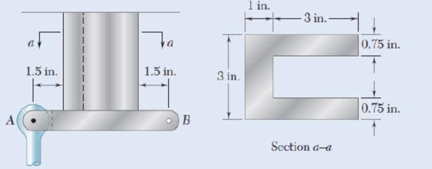
Fig. P4.113
4.114 Solve Prob. 4.113, assuming that the vertical rod is attached at point B instead of point A.
Expert Solution & Answer
Want to see the full answer?
Check out a sample textbook solution
Students have asked these similar questions
A rod must not stretch more than 6 mm when the tension in the wire is 8 kN. Knowing that E = 105 GPa and that the maximum allowable normal stress is 150 MPa, determine the corresponding maximum length of the rod (m).
Two solid cylindrical rods AB and BC are welded together at B and loaded as shown. Knowing that d1 = 50 mm and d2 = 30 mm, find the average normal stress at the midsection of (a) rod AB, (b) rod BC.
Two solid cylindrical rods AB and BC are welded together at B and loaded as shown. Knowing that d1 = 30 mm and d2=50 mm,find the average normal stress at the midsection of (a) rod AB,(b) rod BC.
Chapter 4 Solutions
Mechanics of Materials, 7th Edition
Ch. 4.3 - 4.1 and 4.2 Knowing that the couple shown acts in...Ch. 4.3 - 4.1 and 4.2 Knowing that the couple shown acts in...Ch. 4.3 - Using an allowable stress of 155 MPa, determine...Ch. 4.3 - Solve Prob. 4.3, assuming that the wide-flange...Ch. 4.3 - Using an allowable stress of 16 ksi, determine the...Ch. 4.3 - Knowing that the couple shown acts in a vertical...Ch. 4.3 - 4.7 and 4.8 Two W4 13 rolled sections are welded...Ch. 4.3 - 4.7 and 4.8 Two W4 13 rolled sections are welded...Ch. 4.3 - 4.9 through 4.11 Two vertical forces are applied...Ch. 4.3 - 4.9 through 4.11 Two vertical forces are applied...
Ch. 4.3 - 4.9 through 4.11 Two vertical forces are applied...Ch. 4.3 - Knowing that a beam of the cross section shown is...Ch. 4.3 - Knowing that a beam of the cross section shown is...Ch. 4.3 - Solve Prob. 4.13, assuming that the beam is bent...Ch. 4.3 - Knowing that for the extruded beam shown the...Ch. 4.3 - The beam shown is made of a nylon for which the...Ch. 4.3 - Solve Prob. 4.16, assuming that d = 40 mm.Ch. 4.3 - Knowing that for the beam shown the allowable...Ch. 4.3 - 4.19 and 4.20 Knowing that for the extruded beam...Ch. 4.3 - 4.19 and 4.20 Knowing that for the extruded beam...Ch. 4.3 - Straight rods of 6-mm diameter and 30-m length are...Ch. 4.3 - A 900-mm strip of steel is bent into a full circle...Ch. 4.3 - Straight rods of 0.30-in. diameter and 200-ft...Ch. 4.3 - A 60-Nm couple is applied to the steel bar shown,...Ch. 4.3 - (a) Using an allowable stress of 120 MPa,...Ch. 4.3 - A thick-walled pipe is bent about a horizontal...Ch. 4.3 - A couple M will be applied to a beam of...Ch. 4.3 - A portion of a square bar is removed by milling,...Ch. 4.3 - In Prob. 4.28, determine (a) the value of h for...Ch. 4.3 - For the bar and loading of Concept Application...Ch. 4.3 - Prob. 31PCh. 4.3 - It was assumed in Sec. 4.1B that the normal...Ch. 4.5 - 4.33 and 4.34 A bar having the cross section shown...Ch. 4.5 - 4.33 and 4.34 A bar having the cross section shown...Ch. 4.5 - 4.35 and 4.36 For the composite bar indicated,...Ch. 4.5 - Prob. 36PCh. 4.5 - 4.37 and 4.38 Wooden beams and steel plates are...Ch. 4.5 - 4.37 and 4.38 Wooden beams and steel plates are...Ch. 4.5 - 4.39 and 4.40 A copper strip (Ec = 105 GPa) and an...Ch. 4.5 - 4.39 and 4.40 A copper strip (Ec = 105 GPa) and an...Ch. 4.5 - 4.41 and 4.42 The 6 12-in. timber beam has been...Ch. 4.5 - 4.41 and 4.42 The 6 12-in. timber beam has been...Ch. 4.5 - 4.43 and 4.44 For the composite beam indicated,...Ch. 4.5 - Prob. 44PCh. 4.5 - Prob. 45PCh. 4.5 - Prob. 46PCh. 4.5 - A concrete slab is reinforced by 58-in.-diameter...Ch. 4.5 - Solve Prob. 4.47, assuming that the spacing of the...Ch. 4.5 - The reinforced concrete beam shown is subjected to...Ch. 4.5 - Prob. 50PCh. 4.5 - Knowing that the bending moment in the reinforced...Ch. 4.5 - A concrete beam is reinforced by three steel rods...Ch. 4.5 - The design of a reinforced concrete beam is said...Ch. 4.5 - For the concrete beam shown, the modulus of...Ch. 4.5 - 4.55 and 4.56 Five metal strips, each 0.5 1.5-in....Ch. 4.5 - 4.55 and 4.56 Five metal strips, each 0.5 1.5-in....Ch. 4.5 - The composite beam shown is formed by bonding...Ch. 4.5 - A steel pipe and an aluminum pipe are securely...Ch. 4.5 - The rectangular beam shown is made of a plastic...Ch. 4.5 - Prob. 60PCh. 4.5 - Knowing that M = 250 Nm, determine the maximum...Ch. 4.5 - Knowing that the allowable stress for the beam...Ch. 4.5 - Semicircular grooves of radius r must be milled as...Ch. 4.5 - Prob. 64PCh. 4.5 - A couple of moment M = 2 kNm is to be applied to...Ch. 4.5 - The allowable stress used in the design of a steel...Ch. 4.6 - The prismatic bar shown is made of a steel that is...Ch. 4.6 - Prob. 68PCh. 4.6 - Prob. 69PCh. 4.6 - Prob. 70PCh. 4.6 - The prismatic rod shown is made of a steel that is...Ch. 4.6 - Solve Prob. 4.71, assuming that the couples M and...Ch. 4.6 - 4.73 and 4.74 A beam of the cross section shown is...Ch. 4.6 - 4.73 and 4.74 A beam of the cross section shown is...Ch. 4.6 - 4.75 and 4.76 A beam of the cross section shown is...Ch. 4.6 - Prob. 76PCh. 4.6 - 4.77 through 4.80 For the beam indicated,...Ch. 4.6 - Prob. 78PCh. 4.6 - Prob. 79PCh. 4.6 - 4.77 through 4.80 For the beam indicated,...Ch. 4.6 - 4.81 through 4.83 Determine the plastic moment Mp...Ch. 4.6 - Prob. 82PCh. 4.6 - Prob. 83PCh. 4.6 - Determine the plastic moment Mp of a steel beam of...Ch. 4.6 - Determine the plastic moment Mp of the cross...Ch. 4.6 - Determine the plastic moment Mp of a steel beam of...Ch. 4.6 - Prob. 87PCh. 4.6 - Prob. 88PCh. 4.6 - Prob. 89PCh. 4.6 - Prob. 90PCh. 4.6 - Prob. 91PCh. 4.6 - Prob. 92PCh. 4.6 - Prob. 93PCh. 4.6 - Prob. 94PCh. 4.6 - Prob. 95PCh. 4.6 - Prob. 96PCh. 4.6 - Prob. 97PCh. 4.6 - Prob. 98PCh. 4.7 - Knowing that the magnitude of the horizontal force...Ch. 4.7 - A short wooden post supports a 6-kip axial load as...Ch. 4.7 - Two forces P can be applied separately or at the...Ch. 4.7 - A short 120 180-mm column supports the three...Ch. 4.7 - As many as three axial loads, each of magnitude P...Ch. 4.7 - Two 10-kN forces are applied to a 20 60-mm...Ch. 4.7 - Portions of a 1212-in. square bar have been bent...Ch. 4.7 - Knowing that the allowable stress in section ABD...Ch. 4.7 - A milling operation was used to remove a portion...Ch. 4.7 - A milling operation was used to remove a portion...Ch. 4.7 - The two forces shown are applied to a rigid plate...Ch. 4.7 - Prob. 110PCh. 4.7 - Prob. 111PCh. 4.7 - A short column is made by nailing four 1 4-in....Ch. 4.7 - A vertical rod is attached at point A to the cast...Ch. 4.7 - A vertical rod is attached at point A to the cast...Ch. 4.7 - Knowing that the clamp shown has been tightened...Ch. 4.7 - Prob. 116PCh. 4.7 - Three steel plates, each of 25 150-mm cross...Ch. 4.7 - A vertical force P of magnitude 20 kips is applied...Ch. 4.7 - The four bars shown have the same cross-sectional...Ch. 4.7 - Prob. 120PCh. 4.7 - An eccentric force P is applied as shown to a...Ch. 4.7 - Prob. 122PCh. 4.7 - Prob. 123PCh. 4.7 - Prob. 124PCh. 4.7 - A single vertical force P is applied to a short...Ch. 4.7 - The eccentric axial force P acts at point D, which...Ch. 4.9 - 4.127 through 4.134 The couple M is applied to a...Ch. 4.9 - 4.127 through 4.134 The couple M is applied to a...Ch. 4.9 - 4.127 through 4.134 The couple M is applied to a...Ch. 4.9 - 4.127 through 4.134 The couple M is applied to a...Ch. 4.9 - 4.127 through 4.134 The couple M is applied to a...Ch. 4.9 - 4.127 through 4.134 The couple M is applied to a...Ch. 4.9 - Prob. 133PCh. 4.9 - Prob. 134PCh. 4.9 - 4.135 through 4.140 The couple M acts in a...Ch. 4.9 - 4.135 through 4.140 The couple M acts in a...Ch. 4.9 - Prob. 137PCh. 4.9 - 4.135 through 4.140 The couple M acts in a...Ch. 4.9 - 4.135 through 44.140 The couple M acts in a...Ch. 4.9 - 4.135 through 4.140 The couple M acts in a...Ch. 4.9 - Prob. 141PCh. 4.9 - 4.141 through 4.143 The couple M acts in a...Ch. 4.9 - 4.141 through 4.143 The couple M acts in a...Ch. 4.9 - The tube shown has a uniform wall thickness of 12...Ch. 4.9 - Prob. 145PCh. 4.9 - Knowing that P = 90 kips, determine the largest...Ch. 4.9 - Knowing that a = 1.25 in., determine the largest...Ch. 4.9 - A rigid circular plate of 125-mm radius is...Ch. 4.9 - Prob. 149PCh. 4.9 - A beam having the cross section shown is subjected...Ch. 4.9 - Prob. 151PCh. 4.9 - Prob. 152PCh. 4.9 - Prob. 153PCh. 4.9 - Prob. 154PCh. 4.9 - Prob. 155PCh. 4.9 - Prob. 156PCh. 4.9 - Prob. 157PCh. 4.9 - Prob. 158PCh. 4.9 - A beam of unsymmetric cross section is subjected...Ch. 4.9 - Prob. 160PCh. 4.10 - For the curved bar shown, determine the stress at...Ch. 4.10 - For the curved bar shown, determine the stress at...Ch. 4.10 - Prob. 163PCh. 4.10 - Prob. 164PCh. 4.10 - The curved bar shown has a cross section of 40 60...Ch. 4.10 - Prob. 166PCh. 4.10 - Prob. 167PCh. 4.10 - Prob. 168PCh. 4.10 - The curved bar shown has a cross section of 30 30...Ch. 4.10 - Prob. 170PCh. 4.10 - Prob. 171PCh. 4.10 - Three plates are welded together to form the...Ch. 4.10 - 4.173 and 4.174 Knowing that the maximum allowable...Ch. 4.10 - Prob. 174PCh. 4.10 - Prob. 175PCh. 4.10 - Prob. 176PCh. 4.10 - Prob. 177PCh. 4.10 - Prob. 178PCh. 4.10 - Prob. 179PCh. 4.10 - Knowing that P = 10 kN, determine the stress at...Ch. 4.10 - Prob. 181PCh. 4.10 - Prob. 182PCh. 4.10 - Prob. 183PCh. 4.10 - Prob. 184PCh. 4.10 - Prob. 185PCh. 4.10 - Prob. 186PCh. 4.10 - Prob. 187PCh. 4.10 - Prob. 188PCh. 4.10 - Prob. 189PCh. 4.10 - Prob. 190PCh. 4.10 - For a curved bar of rectagular cross section...Ch. 4 - Two vertical forces are applied to a beam of the...Ch. 4 - Prob. 193RPCh. 4 - Prob. 194RPCh. 4 - Determine the plastic moment Mp of a steel beam of...Ch. 4 - In order to increase corrosion resistance, a...Ch. 4 - The vertical portion of the press shown consists...Ch. 4 - The four forces shown are applied to a rigid plate...Ch. 4 - Prob. 199RPCh. 4 - Prob. 200RPCh. 4 - Three 120 10-mm steel plates have been welded...Ch. 4 - A short length of a W8 31 rolled-steel shape...Ch. 4 - Two thin strips of the same material and same...
Knowledge Booster


Learn more about
Need a deep-dive on the concept behind this application? Look no further. Learn more about this topic, mechanical-engineering and related others by exploring similar questions and additional content below.Similar questions
- A fabric used in air-inflated structures is subjected to a biaxial loading that results in normal stresses ox = 18 ksi and oz = 24 ksi.Knowing that the properties of the fabric can be approximated as E = 12.6 x 10 psi and v = 0.34, determine the change in length of (a) side AB, (b) side BC, (c) diagonal AC.arrow_forwardKnowing that the clamp shown has been tightened until P= 400 N, determine (a) the stress at point A, (b) the stress at point B, (c) the location of the neutral axis of section a-a.arrow_forwardKnowing that the maximum allowable stress is 41 MPa, determine the magnitude of the largest moment M that can be applied to the component shown. The magnitude of the largest moment M that can be applied to the component is kN·m.arrow_forward
- A steel shaft and an aluminum tube are connected to a fixed support and to a rigid disk as shown in the cross section. Knowing that the initial stresses are zero, determine the maximum torque T0 that can be applied to the disk if the allowable stresses are 120 MPa in the steel shaft and 70 MPa in the aluminum tube. Use G= 77 GPa for steel and G = 27 GPa for aluminum.arrow_forwardKnowing that the couple shown acts in a vertical plane, determine the stress at (a) point A, (b) point B.arrow_forwardThe centric force P is applied to a short post as shown. Knowing that the stresses on plane a–a are σ=215 ksi and τ= 5 ksi, determine (a) the angle β that plane a–a forms with the horizontal, (b) the maxi-mum compressive stress in the postarrow_forward
- A fabric used in air-inflated structures is subjected to a biaxial load-ing that results in normal stresses σx=120 MPa and σz =160 MPa. Knowing that the properties of the fabric can be approximated as E=87 GPa and ν= 0.34, determine the change in length of (a) side AB, (b) side BC, (c) diagonal AC.arrow_forwardA cast-iron machine part is acted upon by the 3 kN-m couple shown. Know-ing that E= 165 GPa and neglecting the effect of fillets, determine (a) the maximum tensile and compressive stresses in the casting and (b) the radius of curvature of the castingarrow_forwardA vertical rod is attached at point A to the cast iron hanger shown. Knowing that the allowable stresses in the hanger are σall=15 ksi and σall=– 12 ksi, determine the largest downward force and the larg-est upward force that can be exerted by the rod.arrow_forward
- Straight rods of 0.30-in. diameter and 200-ft length are sometimes used to clear underground conduits of obstructions or to thread wires through a new conduit. The rods are made of high-strength steel and, for storage and transportation, are wrapped on spools of 5-ft diameter. Assuming that the yield strength is not exceeded, determine (a) the maximum stress in a rod, when the rod, which was initially straight, is wrapped on the spool, (b) the corresponding bending moment in the rod. Use E= 29 * 106 psi.arrow_forwardThe four forces shown are applied to a rigid plate supported by a solid steel post of radius a. Knowing that P= 24 kips and a= 1.6 in., determine the maximum stress in the post when (a) the force at D is removed, (b) the forces at C and D are removedarrow_forwardA timber beam AB of length L and rectangular cross section carries a single concentrated load P at its midpoint C. (a) Show that the ratio Tm/ m of the maximum values of the shearing and normal stresses in the beam is equal to h/2L, where h and L are, respectively, the depth and the length of the beam. (b) Determine the depth h and the width b of the beam, knowing that L = 2 m, P = 40 kN, 7m = 960 kPa, and om = 12 MPa.arrow_forward
arrow_back_ios
SEE MORE QUESTIONS
arrow_forward_ios
Recommended textbooks for you
 Elements Of ElectromagneticsMechanical EngineeringISBN:9780190698614Author:Sadiku, Matthew N. O.Publisher:Oxford University Press
 Mechanics of Materials (10th Edition)Mechanical EngineeringISBN:9780134319650Author:Russell C. HibbelerPublisher:PEARSON
 Thermodynamics: An Engineering ApproachMechanical EngineeringISBN:9781259822674Author:Yunus A. Cengel Dr., Michael A. BolesPublisher:McGraw-Hill Education
 Control Systems EngineeringMechanical EngineeringISBN:9781118170519Author:Norman S. NisePublisher:WILEY
 Mechanics of Materials (MindTap Course List)Mechanical EngineeringISBN:9781337093347Author:Barry J. Goodno, James M. GerePublisher:Cengage Learning
 Engineering Mechanics: StaticsMechanical EngineeringISBN:9781118807330Author:James L. Meriam, L. G. Kraige, J. N. BoltonPublisher:WILEY
Elements Of Electromagnetics
Mechanical Engineering
ISBN:9780190698614
Author:Sadiku, Matthew N. O.
Publisher:Oxford University Press
Mechanics of Materials (10th Edition)
Mechanical Engineering
ISBN:9780134319650
Author:Russell C. Hibbeler
Publisher:PEARSON
Thermodynamics: An Engineering Approach
Mechanical Engineering
ISBN:9781259822674
Author:Yunus A. Cengel Dr., Michael A. Boles
Publisher:McGraw-Hill Education
Control Systems Engineering
Mechanical Engineering
ISBN:9781118170519
Author:Norman S. Nise
Publisher:WILEY
Mechanics of Materials (MindTap Course List)
Mechanical Engineering
ISBN:9781337093347
Author:Barry J. Goodno, James M. Gere
Publisher:Cengage Learning
Engineering Mechanics: Statics
Mechanical Engineering
ISBN:9781118807330
Author:James L. Meriam, L. G. Kraige, J. N. Bolton
Publisher:WILEY
Differences between Temporary Joining and Permanent Joining.; Author: Academic Gain Tutorials;https://www.youtube.com/watch?v=PTr8QZhgXyg;License: Standard Youtube License