
Mechanics of Materials, 7th Edition
7th Edition
ISBN: 9780073398235
Author: Ferdinand P. Beer, E. Russell Johnston Jr., John T. DeWolf, David F. Mazurek
Publisher: McGraw-Hill Education
expand_more
expand_more
format_list_bulleted
Concept explainers
Videos
Textbook Question
Chapter 4.3, Problem 23P
Straight rods of 0.30-in. diameter and 200-ft length are sometimes used to clear underground conduits of obstructions or to thread wires through a new conduit. The rods are made of high-strength steel and, for storage and transportation, are wrapped on spools of 5-ft diameter. Assuming that the yield strength is not exceeded, determine (a) the maximum stress in a rod, when the rod, which is initially straight, is wrapped on a spool, (b) the corresponding bending moment in the rod. Use E = 29 × l06 psi.
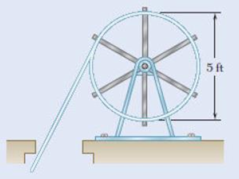
Fig. P4.23
Expert Solution & Answer
Want to see the full answer?
Check out a sample textbook solution
Students have asked these similar questions
A standard-weight steel pipe of 12-in. nominal diameter carries water under a pressure of 400 psi. (a) Knowing that the outside diameter is 12.75 in. and the wall thickness is 0.375 in., determine the maximum tensile stress in the pipe. (b) Solve part a, assuming that an extra-strong pipe is used, of 12.75-in. outside diameter and 0.5-in. wall thickness.
Three wooden planks are fastened together by a series of bolts to form a column. The diameter of each bolt is 12 mm and the inner diameter of each washer is 16 mm, which is slightly larger than the diameter of the holes in the planks. Determine the smallest allowable outer diameter d of the washers, knowing that the average normal stress in the bolts is 36 MPa and that the bearing stress between the washers and the planks must not exceed 8.5 MPa.
The driveshaft of an automobile is being designed to transmit 238 hp at 3790 rpm. Determine the minimum diameter d required for a solid steel shaft if the allowable shear stress in the shaft is not to exceed 5700 psi.
Chapter 4 Solutions
Mechanics of Materials, 7th Edition
Ch. 4.3 - 4.1 and 4.2 Knowing that the couple shown acts in...Ch. 4.3 - 4.1 and 4.2 Knowing that the couple shown acts in...Ch. 4.3 - Using an allowable stress of 155 MPa, determine...Ch. 4.3 - Solve Prob. 4.3, assuming that the wide-flange...Ch. 4.3 - Using an allowable stress of 16 ksi, determine the...Ch. 4.3 - Knowing that the couple shown acts in a vertical...Ch. 4.3 - 4.7 and 4.8 Two W4 13 rolled sections are welded...Ch. 4.3 - 4.7 and 4.8 Two W4 13 rolled sections are welded...Ch. 4.3 - 4.9 through 4.11 Two vertical forces are applied...Ch. 4.3 - 4.9 through 4.11 Two vertical forces are applied...
Ch. 4.3 - 4.9 through 4.11 Two vertical forces are applied...Ch. 4.3 - Knowing that a beam of the cross section shown is...Ch. 4.3 - Knowing that a beam of the cross section shown is...Ch. 4.3 - Solve Prob. 4.13, assuming that the beam is bent...Ch. 4.3 - Knowing that for the extruded beam shown the...Ch. 4.3 - The beam shown is made of a nylon for which the...Ch. 4.3 - Solve Prob. 4.16, assuming that d = 40 mm.Ch. 4.3 - Knowing that for the beam shown the allowable...Ch. 4.3 - 4.19 and 4.20 Knowing that for the extruded beam...Ch. 4.3 - 4.19 and 4.20 Knowing that for the extruded beam...Ch. 4.3 - Straight rods of 6-mm diameter and 30-m length are...Ch. 4.3 - A 900-mm strip of steel is bent into a full circle...Ch. 4.3 - Straight rods of 0.30-in. diameter and 200-ft...Ch. 4.3 - A 60-Nm couple is applied to the steel bar shown,...Ch. 4.3 - (a) Using an allowable stress of 120 MPa,...Ch. 4.3 - A thick-walled pipe is bent about a horizontal...Ch. 4.3 - A couple M will be applied to a beam of...Ch. 4.3 - A portion of a square bar is removed by milling,...Ch. 4.3 - In Prob. 4.28, determine (a) the value of h for...Ch. 4.3 - For the bar and loading of Concept Application...Ch. 4.3 - Prob. 31PCh. 4.3 - It was assumed in Sec. 4.1B that the normal...Ch. 4.5 - 4.33 and 4.34 A bar having the cross section shown...Ch. 4.5 - 4.33 and 4.34 A bar having the cross section shown...Ch. 4.5 - 4.35 and 4.36 For the composite bar indicated,...Ch. 4.5 - Prob. 36PCh. 4.5 - 4.37 and 4.38 Wooden beams and steel plates are...Ch. 4.5 - 4.37 and 4.38 Wooden beams and steel plates are...Ch. 4.5 - 4.39 and 4.40 A copper strip (Ec = 105 GPa) and an...Ch. 4.5 - 4.39 and 4.40 A copper strip (Ec = 105 GPa) and an...Ch. 4.5 - 4.41 and 4.42 The 6 12-in. timber beam has been...Ch. 4.5 - 4.41 and 4.42 The 6 12-in. timber beam has been...Ch. 4.5 - 4.43 and 4.44 For the composite beam indicated,...Ch. 4.5 - Prob. 44PCh. 4.5 - Prob. 45PCh. 4.5 - Prob. 46PCh. 4.5 - A concrete slab is reinforced by 58-in.-diameter...Ch. 4.5 - Solve Prob. 4.47, assuming that the spacing of the...Ch. 4.5 - The reinforced concrete beam shown is subjected to...Ch. 4.5 - Prob. 50PCh. 4.5 - Knowing that the bending moment in the reinforced...Ch. 4.5 - A concrete beam is reinforced by three steel rods...Ch. 4.5 - The design of a reinforced concrete beam is said...Ch. 4.5 - For the concrete beam shown, the modulus of...Ch. 4.5 - 4.55 and 4.56 Five metal strips, each 0.5 1.5-in....Ch. 4.5 - 4.55 and 4.56 Five metal strips, each 0.5 1.5-in....Ch. 4.5 - The composite beam shown is formed by bonding...Ch. 4.5 - A steel pipe and an aluminum pipe are securely...Ch. 4.5 - The rectangular beam shown is made of a plastic...Ch. 4.5 - Prob. 60PCh. 4.5 - Knowing that M = 250 Nm, determine the maximum...Ch. 4.5 - Knowing that the allowable stress for the beam...Ch. 4.5 - Semicircular grooves of radius r must be milled as...Ch. 4.5 - Prob. 64PCh. 4.5 - A couple of moment M = 2 kNm is to be applied to...Ch. 4.5 - The allowable stress used in the design of a steel...Ch. 4.6 - The prismatic bar shown is made of a steel that is...Ch. 4.6 - Prob. 68PCh. 4.6 - Prob. 69PCh. 4.6 - Prob. 70PCh. 4.6 - The prismatic rod shown is made of a steel that is...Ch. 4.6 - Solve Prob. 4.71, assuming that the couples M and...Ch. 4.6 - 4.73 and 4.74 A beam of the cross section shown is...Ch. 4.6 - 4.73 and 4.74 A beam of the cross section shown is...Ch. 4.6 - 4.75 and 4.76 A beam of the cross section shown is...Ch. 4.6 - Prob. 76PCh. 4.6 - 4.77 through 4.80 For the beam indicated,...Ch. 4.6 - Prob. 78PCh. 4.6 - Prob. 79PCh. 4.6 - 4.77 through 4.80 For the beam indicated,...Ch. 4.6 - 4.81 through 4.83 Determine the plastic moment Mp...Ch. 4.6 - Prob. 82PCh. 4.6 - Prob. 83PCh. 4.6 - Determine the plastic moment Mp of a steel beam of...Ch. 4.6 - Determine the plastic moment Mp of the cross...Ch. 4.6 - Determine the plastic moment Mp of a steel beam of...Ch. 4.6 - Prob. 87PCh. 4.6 - Prob. 88PCh. 4.6 - Prob. 89PCh. 4.6 - Prob. 90PCh. 4.6 - Prob. 91PCh. 4.6 - Prob. 92PCh. 4.6 - Prob. 93PCh. 4.6 - Prob. 94PCh. 4.6 - Prob. 95PCh. 4.6 - Prob. 96PCh. 4.6 - Prob. 97PCh. 4.6 - Prob. 98PCh. 4.7 - Knowing that the magnitude of the horizontal force...Ch. 4.7 - A short wooden post supports a 6-kip axial load as...Ch. 4.7 - Two forces P can be applied separately or at the...Ch. 4.7 - A short 120 180-mm column supports the three...Ch. 4.7 - As many as three axial loads, each of magnitude P...Ch. 4.7 - Two 10-kN forces are applied to a 20 60-mm...Ch. 4.7 - Portions of a 1212-in. square bar have been bent...Ch. 4.7 - Knowing that the allowable stress in section ABD...Ch. 4.7 - A milling operation was used to remove a portion...Ch. 4.7 - A milling operation was used to remove a portion...Ch. 4.7 - The two forces shown are applied to a rigid plate...Ch. 4.7 - Prob. 110PCh. 4.7 - Prob. 111PCh. 4.7 - A short column is made by nailing four 1 4-in....Ch. 4.7 - A vertical rod is attached at point A to the cast...Ch. 4.7 - A vertical rod is attached at point A to the cast...Ch. 4.7 - Knowing that the clamp shown has been tightened...Ch. 4.7 - Prob. 116PCh. 4.7 - Three steel plates, each of 25 150-mm cross...Ch. 4.7 - A vertical force P of magnitude 20 kips is applied...Ch. 4.7 - The four bars shown have the same cross-sectional...Ch. 4.7 - Prob. 120PCh. 4.7 - An eccentric force P is applied as shown to a...Ch. 4.7 - Prob. 122PCh. 4.7 - Prob. 123PCh. 4.7 - Prob. 124PCh. 4.7 - A single vertical force P is applied to a short...Ch. 4.7 - The eccentric axial force P acts at point D, which...Ch. 4.9 - 4.127 through 4.134 The couple M is applied to a...Ch. 4.9 - 4.127 through 4.134 The couple M is applied to a...Ch. 4.9 - 4.127 through 4.134 The couple M is applied to a...Ch. 4.9 - 4.127 through 4.134 The couple M is applied to a...Ch. 4.9 - 4.127 through 4.134 The couple M is applied to a...Ch. 4.9 - 4.127 through 4.134 The couple M is applied to a...Ch. 4.9 - Prob. 133PCh. 4.9 - Prob. 134PCh. 4.9 - 4.135 through 4.140 The couple M acts in a...Ch. 4.9 - 4.135 through 4.140 The couple M acts in a...Ch. 4.9 - Prob. 137PCh. 4.9 - 4.135 through 4.140 The couple M acts in a...Ch. 4.9 - 4.135 through 44.140 The couple M acts in a...Ch. 4.9 - 4.135 through 4.140 The couple M acts in a...Ch. 4.9 - Prob. 141PCh. 4.9 - 4.141 through 4.143 The couple M acts in a...Ch. 4.9 - 4.141 through 4.143 The couple M acts in a...Ch. 4.9 - The tube shown has a uniform wall thickness of 12...Ch. 4.9 - Prob. 145PCh. 4.9 - Knowing that P = 90 kips, determine the largest...Ch. 4.9 - Knowing that a = 1.25 in., determine the largest...Ch. 4.9 - A rigid circular plate of 125-mm radius is...Ch. 4.9 - Prob. 149PCh. 4.9 - A beam having the cross section shown is subjected...Ch. 4.9 - Prob. 151PCh. 4.9 - Prob. 152PCh. 4.9 - Prob. 153PCh. 4.9 - Prob. 154PCh. 4.9 - Prob. 155PCh. 4.9 - Prob. 156PCh. 4.9 - Prob. 157PCh. 4.9 - Prob. 158PCh. 4.9 - A beam of unsymmetric cross section is subjected...Ch. 4.9 - Prob. 160PCh. 4.10 - For the curved bar shown, determine the stress at...Ch. 4.10 - For the curved bar shown, determine the stress at...Ch. 4.10 - Prob. 163PCh. 4.10 - Prob. 164PCh. 4.10 - The curved bar shown has a cross section of 40 60...Ch. 4.10 - Prob. 166PCh. 4.10 - Prob. 167PCh. 4.10 - Prob. 168PCh. 4.10 - The curved bar shown has a cross section of 30 30...Ch. 4.10 - Prob. 170PCh. 4.10 - Prob. 171PCh. 4.10 - Three plates are welded together to form the...Ch. 4.10 - 4.173 and 4.174 Knowing that the maximum allowable...Ch. 4.10 - Prob. 174PCh. 4.10 - Prob. 175PCh. 4.10 - Prob. 176PCh. 4.10 - Prob. 177PCh. 4.10 - Prob. 178PCh. 4.10 - Prob. 179PCh. 4.10 - Knowing that P = 10 kN, determine the stress at...Ch. 4.10 - Prob. 181PCh. 4.10 - Prob. 182PCh. 4.10 - Prob. 183PCh. 4.10 - Prob. 184PCh. 4.10 - Prob. 185PCh. 4.10 - Prob. 186PCh. 4.10 - Prob. 187PCh. 4.10 - Prob. 188PCh. 4.10 - Prob. 189PCh. 4.10 - Prob. 190PCh. 4.10 - For a curved bar of rectagular cross section...Ch. 4 - Two vertical forces are applied to a beam of the...Ch. 4 - Prob. 193RPCh. 4 - Prob. 194RPCh. 4 - Determine the plastic moment Mp of a steel beam of...Ch. 4 - In order to increase corrosion resistance, a...Ch. 4 - The vertical portion of the press shown consists...Ch. 4 - The four forces shown are applied to a rigid plate...Ch. 4 - Prob. 199RPCh. 4 - Prob. 200RPCh. 4 - Three 120 10-mm steel plates have been welded...Ch. 4 - A short length of a W8 31 rolled-steel shape...Ch. 4 - Two thin strips of the same material and same...
Knowledge Booster


Learn more about
Need a deep-dive on the concept behind this application? Look no further. Learn more about this topic, mechanical-engineering and related others by exploring similar questions and additional content below.Similar questions
- Two steel plates are to be held together by means of 16-mm-diameter high-strength steel bolts fitting snugly inside cylindrical brass spacers.Knowing that the average normal stress must not exceed 200 MPa in the bolts and 130 MPa in the spacers, determine the outer diameter of the spacers that yields the most economical and safe design.arrow_forwardAn open-link chain is obtained by bending low-carbon steel rods of 0.5-in. diameter into the shape shown (Fig. ). Knowing that the chain carries a load of 160 lb, determine (a) the largest tensile and compressive stresses in the straight portion of a link, (b) the distance between the cen-troidal and the neutral axis of a cross sectionarrow_forwardA steel pipe of 400-mm outer diameter is fabricated from 10-mm-thick plate by welding along a helix that forms an angle of 20°with a plane perpendicular to the axis of the pipe. Knowing that the maximum allowable normal and shearing stresses in the directions respectively normal and tangential to the weld are σ = 60 MPa and τ = 36 MPa, determine the magnitude P of the largest axial force that can be applied to the pipe.arrow_forward
- A spherical gas container made of steel has a 20-ft outer diameter and a wall thickness of 7/16 in. Knowing that the internal pressure is 75 psi, determine the maximum normal stress and the maximum shearing stress in the container.arrow_forwardA steel shaft and an aluminum tube are connected to a fixed support and to a rigid disk as shown in the cross section. Knowing that the initial stresses are zero, determine the maximum torque T0 that can be applied to the disk if the allowable stresses are 120 MPa in the steel shaft and 70 MPa in the aluminum tube. Use G= 77 GPa for steel and G = 27 GPa for aluminum.arrow_forwardA steel plate 5/16 in. thick is embedded in a horizontal concrete slab and is used to anchor a high-strength vertical cable as shown. The diameter of the hole in the plate is 3/4in., the ultimate strength of the steel used is 36 ksi, and the ultimate bonding stress between plate and concrete is 300 psi. Knowing that a factor of safety of 3.60 is desired when P = 2.5 kips, determine (a) the required width a of the plate,(b) the minimum depth b to which a plate of that width should be embedded in the concrete slab. (Neglect the normal stresses betweenthe concrete and the lower end of the plate.)arrow_forward
- The 4.5-ft concrete post is reinforced with six steel bars, each with a 118-in. diameter. Knowing that Es5 29 3 106 psi and Ec5 4.2 3 106 psi, determine the normal stresses in the steel and in the concrete when a 350-kip axial centric force P is applied to the postarrow_forwardTwo fork end pieces are to be joined together by a single steel pin of 25mm diameter and they are required to transmit 50 kN. Determine the minimum cross-sectional area of material required in one branch of either fork if the stress in the fork material is not to exceed 180 MN/m2. What will be the maximum shear stress in the pin?arrow_forwardA 5-kN tensile load will be applied to a 50-m length of steel wire with E = 200 GPa. Determine the smallest diameter wire that can be used, knowing that the normal stress must not exceed 150 MPa and that the increase in length of the wire must not exceed 25 mm.arrow_forward
- A flange coupling connects two 2 inch diameter shaft. The flanges are fitted by 6 bolts on a 7 “ bolt circle. If the shaft rotates at 300 rpm and transmit 45 hp, determine the required bolt diameter when allowable shear stress of 11,000 psi.arrow_forwardIn the steel structure shown, a 6-mm-diameter pin is used at C and 12-mm-diameter pins are used at B and D. The ultimate shearing stress is 150 MPa at all connections, and the ultimate normal stress is 350 MPa in link BD. Knowing that a factor of safety of 3.0 is desired, determine the largest load P that can be applied at A. Note that link BD is not reinforced around the pin holes. The largest load P that can be applied at A is kN.arrow_forwardSolve Prob A rod consisting of two cylindrical portions AB and BC is restrained at both ends. Portion AB is made of steel (Es5 29 3 106 psi, αs5 6.5 3 10–6/°F) and portion BC is made of aluminum (Ea5 10.4 3 106psi, αa5 13.3 3 10–6/°F). Knowing that the rod is initially unstressed, determine (a) the normal stresses induced in portions AB and BC by a temperature rise of 70°F, (b) the corresponding deflection of point B assuming that portion AB of the composite rod is made of aluminum and portion BC is made of steel.arrow_forward
arrow_back_ios
SEE MORE QUESTIONS
arrow_forward_ios
Recommended textbooks for you
 Elements Of ElectromagneticsMechanical EngineeringISBN:9780190698614Author:Sadiku, Matthew N. O.Publisher:Oxford University Press
 Mechanics of Materials (10th Edition)Mechanical EngineeringISBN:9780134319650Author:Russell C. HibbelerPublisher:PEARSON
 Thermodynamics: An Engineering ApproachMechanical EngineeringISBN:9781259822674Author:Yunus A. Cengel Dr., Michael A. BolesPublisher:McGraw-Hill Education
 Control Systems EngineeringMechanical EngineeringISBN:9781118170519Author:Norman S. NisePublisher:WILEY
 Mechanics of Materials (MindTap Course List)Mechanical EngineeringISBN:9781337093347Author:Barry J. Goodno, James M. GerePublisher:Cengage Learning
 Engineering Mechanics: StaticsMechanical EngineeringISBN:9781118807330Author:James L. Meriam, L. G. Kraige, J. N. BoltonPublisher:WILEY
Elements Of Electromagnetics
Mechanical Engineering
ISBN:9780190698614
Author:Sadiku, Matthew N. O.
Publisher:Oxford University Press
Mechanics of Materials (10th Edition)
Mechanical Engineering
ISBN:9780134319650
Author:Russell C. Hibbeler
Publisher:PEARSON
Thermodynamics: An Engineering Approach
Mechanical Engineering
ISBN:9781259822674
Author:Yunus A. Cengel Dr., Michael A. Boles
Publisher:McGraw-Hill Education
Control Systems Engineering
Mechanical Engineering
ISBN:9781118170519
Author:Norman S. Nise
Publisher:WILEY
Mechanics of Materials (MindTap Course List)
Mechanical Engineering
ISBN:9781337093347
Author:Barry J. Goodno, James M. Gere
Publisher:Cengage Learning
Engineering Mechanics: Statics
Mechanical Engineering
ISBN:9781118807330
Author:James L. Meriam, L. G. Kraige, J. N. Bolton
Publisher:WILEY
Everything About COMBINED LOADING in 10 Minutes! Mechanics of Materials; Author: Less Boring Lectures;https://www.youtube.com/watch?v=N-PlI900hSg;License: Standard youtube license