
Videos
(a)
Find the residual stress at
(a)
Answer to Problem 90P
The residual stress is
Explanation of Solution
Given information:
The yield stress for the beam is
The Young’s modulus of steel is
Calculation:
Show the cross-section of the beam as shown in Figure 1.
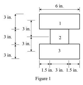
Refer Figure 1.
Calculate the area of the cross section
Here, b is the width of the cross section and d is the depth of the cross section.
Calculate the area of the portion (1)
Substitute
Calculate the area of the portion (2)
Substitute
Calculate the moment of inertia
Calculate the moment of inertia of portion (1)
Substitute
Calculate the moment of inertia of portion (2)
Substitute
Calculate the total moment of inertia
Substitute
Calculate the centroid (c) as shown below.
Substitute
Sketch the stress acting on the cross-section of the beam as shown in Figure 2.
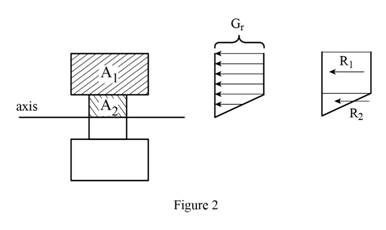
Refer Figure 2.
Calculate the area of the portion (2)
Substitute
Calculate the reaction applied to portion (1)
Substitute
Calculate the reaction applied to portion (2)
Substitute
Calculate the moment
Substitute
Calculate the stress
Substitute
Calculate the stress
Substitute
Calculate the residual stress at
Substitute
Calculate the residual stress at
Substitute
Sketch the stress distribution as shown in Figure 3.
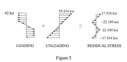
Hence, the residual stress is
(b)
Find the point where the residual stress is zero.
(b)
Answer to Problem 90P
The point where the residual stress is zero is
Explanation of Solution
Given information:
The yield stress for the beam is
The Young’s modulus of steel is
Calculation:
Consider that the residual stress
Calculate the yield stress
Calculate the point where the residual stress is zero as shown below.
Substitute
Substitute
Therefore, the point where the residual stress is zero is
(c)
Find the radius of curvature corresponding to the permanent deformation of the bar.
(c)
Answer to Problem 90P
The radius of curvature is
Explanation of Solution
Given information:
The yield stress for the beam is
The Young’s modulus of steel is
Calculation:
Refer to part (a).
The residual stress
Calculate the radius of curvature
Calculate the point where the residual stress is zero as shown below.
Substitute
Therefore, the radius of curvature is
Want to see more full solutions like this?
Chapter 4 Solutions
Mechanics of Materials, 7th Edition


- A rod must not stretch more than 6 mm when the tension in the wire is 8 kN. Knowing that E = 105 GPa and that the maximum allowable normal stress is 150 MPa, determine the corresponding maximum length of the rod (m).arrow_forwardTwo cylindrical rods, one of steel and the other of brass, are joined at C and restrained by rigid supports at A and E. The steel rod has a length of 300 mm while the brass rod has a length of 200 mm. The diameters of the rods are shown in the figure below. A force of 60 kN is applied at point B of the steel segment. For the loading shown and knowing that modulus of elasticity values for steel and brass are respectively Es = 200 GPa and Eb = 105 GPa, determine a.) The reactions at A and E: RA and RE. b.) The deflection of point C from its original location. how to doarrow_forwardThe structure shown consists of a single member ABCDE with a pin support at A and a roller support at E. Points B and D are at the midpoints of their respective segments. Determine the internal shear force acting on I which are located immediately to the left of C. Take N = 1 kN, O = 3 kN, and P = 4 kN.arrow_forward
- Straight rods of 0.30-in. diameter and 200-ft length are sometimes used to clear underground conduits of obstructions or to thread wires through a new conduit. The rods are made of high-strength steel and, for storage and transportation, are wrapped on spools of 5-ft diameter. Assuming that the yield strength is not exceeded, determine (a) the maximum stress in a rod, when the rod, which was initially straight, is wrapped on the spool, (b) the corresponding bending moment in the rod. Use E= 29 * 106 psi.arrow_forwardA fabric used in air-inflated structures is subjected to a biaxial load-ing that results in normal stresses σx=120 MPa and σz =160 MPa. Knowing that the properties of the fabric can be approximated as E=87 GPa and ν= 0.34, determine the change in length of (a) side AB, (b) side BC, (c) diagonal AC.arrow_forwardThree wooden planks are fastened together by a series of bolts to form a column. The diameter of each bolt is 12 mm and the inner diameter of each washer is 16 mm, which is slightly larger than the diameter of the holes in the planks. Determine the smallest allowable outer diameter d of the washers, knowing that the average normal stress in the bolts is 36 MPa and that the bearing stress between the washers and the planks must not exceed 8.5 MPa.arrow_forward
- Five metal strips, each of 0.5 * 1.5-in. cross section, are bonded together to form the composite beam shown. The modulus of elasticity is 30* 106 psi for the steel, 15 *106 psi for the brass, 10 *106 psi for the aluminum. Knowing that the beam is bent about a horizontal axis by a couple of moment 12 kip·in., determine (a) the maximum stress in each of the three metals, (b) the radius of curvature of the composite beam.arrow_forwardKnowing that the maximum allowable stress is 41 MPa, determine the magnitude of the largest moment M that can be applied to the component shown. The magnitude of the largest moment M that can be applied to the component is kN·m.arrow_forwardA 50-kN force is subjected to a lap joint fastened by three 20-mm diameter rivets.(a) the shearing stress in each rivet.(b) the bearing stress in each plate.(c) the maximum average tensile stress in each plate. Assume that the axial load P is distributed equally amongthe three rivets. equally among the three rivets.arrow_forward
- Knowing that the couple shown acts in a vertical plane, determine the stress at (a) point A, (b) point B.arrow_forwardTo determine the state of stress in a solid rod using the principle of superposition. A solid rod has a diameter of e� = 55 mmmm and is subjected to the loading shown. Let a� = 200 mmmm , b� = 220 mmmm , c� = 350 mmmm , d� = 250 mmmm , and P� = 3.0 kNkN . Take point A to be at the top of the circular cross-section. As shown (Figure 2), a cut was made at A to determine the resultant internal loadings. Determine the moment about the x axis, Mx��. b) Part B - Moment about the z axis at A Part C - Stress due to the normal force To find the state of stress at A, the principle of superposition must be used. If the rod has a diameter of 55 mm , find the stress σA�� due to the normal force. Part D - Stress due to the bending moment about the x axis To find the state of stress at A, the principle of superposition must be used. If the rod has a diameter of 55 mm , find the stress σA�� due to the bending moment about the x axis.arrow_forwardA cast-iron machine part is acted upon by the 3 kN-m couple shown. Know-ing that E= 165 GPa and neglecting the effect of fillets, determine (a) the maximum tensile and compressive stresses in the casting and (b) the radius of curvature of the castingarrow_forward
 Elements Of ElectromagneticsMechanical EngineeringISBN:9780190698614Author:Sadiku, Matthew N. O.Publisher:Oxford University Press
 Mechanics of Materials (10th Edition)Mechanical EngineeringISBN:9780134319650Author:Russell C. HibbelerPublisher:PEARSON
 Thermodynamics: An Engineering ApproachMechanical EngineeringISBN:9781259822674Author:Yunus A. Cengel Dr., Michael A. BolesPublisher:McGraw-Hill Education
 Control Systems EngineeringMechanical EngineeringISBN:9781118170519Author:Norman S. NisePublisher:WILEY
 Mechanics of Materials (MindTap Course List)Mechanical EngineeringISBN:9781337093347Author:Barry J. Goodno, James M. GerePublisher:Cengage Learning
 Engineering Mechanics: StaticsMechanical EngineeringISBN:9781118807330Author:James L. Meriam, L. G. Kraige, J. N. BoltonPublisher:WILEY