
CONNECT F/SHIGLEY'S MECH.ENGR.DESIGN>I<
10th Edition
ISBN: 9781260058499
Author: BUDYNAS
Publisher: INTER MCG
expand_more
expand_more
format_list_bulleted
Concept explainers
Videos
Textbook Question
Chapter 6, Problem 37P
6-37* to 6-46For the problem specified in the build upon the results of the original problem to determine the minimum factor of safety for fatigue based on infinite life, using the modified Goodman criterion. The shaft rotates at a constant speed, has a constant diameter, and is made from cold-drawn AISI 1018 steel.
| Problem Number | Original Problem, Page Number |
| 6-37* | 3-68, 151 |
| 6-38* | 3-69, 151 |
| 6-39* | 3-70, 151 |
| 6-40* | 3-71, 151 |
| 6-41* | 3-72, 152 |
| 6-42* | 3-73, 152 |
| 6-43* | 3-74, 152 |
| 6-44* | 3-76, 153 |
| 6-45* | 3-77, 153 |
| 6-46* | 3-79, 153 |
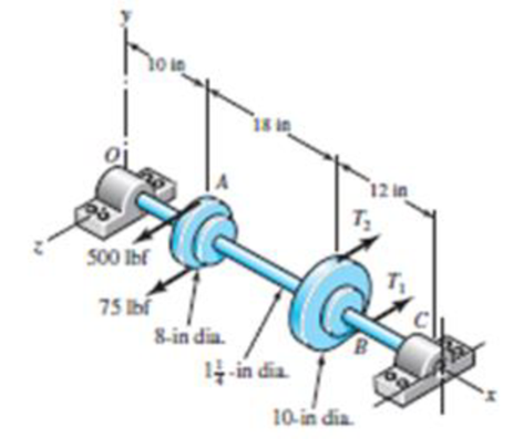
Problem 3-68*
Expert Solution & Answer
Want to see the full answer?
Check out a sample textbook solution
Students have asked these similar questions
A 1-in-diameter solid round bar has a groove 0.1-in deep with a 0.1-in radius machined into it. The bar is made of AISI 1020 CD steel and is subjected to a purely reversing torque of 1800 lb-in. For the S-N diagram of this material, let f=0.9.
Estimate the number of cycles to failure.
If the bar is also placed in an environment with a temperature of 750 F, estimate the number of cycles to failure
A rotating shaft of 40×4 mm AISI 1018 cold-drawn steel tubing has a 6 mm diameter hole drilled transversely through it. Estimate the factor of safety guarding against fatigue and static failures using the Gerber and Langer failure criteria for the following loading conditions: a. The shaft is subjected to a completely reversed torque of 120 N.m in phase with a completely reversed bending moment of 150 N.m. b. The shaft is subjected to a pulsating torque fluctuating from 20 to 160 N.m and as steady bending moment of 150 N.m.
A certain steel shafting material has an ultimate strength of 93 ksi, a notch radius of 0.25 inch, and a stress concentration factor of 2.5 at its pitch. Determine the fatigue-strength reduction factor for a life of 166,077 cycles only
Chapter 6 Solutions
CONNECT F/SHIGLEY'S MECH.ENGR.DESIGN>I<
Ch. 6 - A 10-mm steel drill rod was heat-treated and...Ch. 6 - Prob. 2PCh. 6 - A steel rotating-beam test specimen has an...Ch. 6 - A steel rotating-beam test specimen has an...Ch. 6 - A steel rotating-beam test specimen has an...Ch. 6 - Repeat Prob. 6-5 with the specimen having an...Ch. 6 - A steel rotating-beam test specimen has an...Ch. 6 - Derive Eq. (6-17). Rearrange the equation to solve...Ch. 6 - For the interval 103 N 106 cycles, develop an...Ch. 6 - Estimate the endurance strength of a...
Ch. 6 - Two steels are being considered for manufacture of...Ch. 6 - A 1-in-diamctcr solid round bar has a groove...Ch. 6 - A solid square rod is cantilevered at one end. The...Ch. 6 - A rectangular bar is cut from an AISI 1020...Ch. 6 - A solid round bar with diameter of 2 in has a...Ch. 6 - The rotating shaft shown in the figure is machined...Ch. 6 - The shaft shown in the figure is machined from...Ch. 6 - Solve Prob. 6-17 except with forces F1 = 1200 lbf...Ch. 6 - Bearing reactions R1 and R2 are exerted on the...Ch. 6 - A bar of steel has the minimum properties Se = 40...Ch. 6 - Repeat Prob. 6-20 but with a steady torsional...Ch. 6 - Repeat Prob. 6-20 but with a steady torsional...Ch. 6 - Repeat Prob. 6-20 but with an alternating...Ch. 6 - A bar of steel has the minimum properties Se = 40...Ch. 6 - The cold-drawn AISI KUO steel bar shown in the...Ch. 6 - Repeat Prob. 6-25 for a load that fluctuates from...Ch. 6 - An M14 2 hex-head bolt with a nut is used to...Ch. 6 - The figure shows a formed round-wire cantilever...Ch. 6 - The figure is a drawing of a 4- by 20-mm latching...Ch. 6 - The figure shows the free-body diagram of a...Ch. 6 - Solve Prob. 6-30 except let w1 = 2.5 in. w2 = l.5...Ch. 6 - For the part in Prob. 630, recommend a fillet...Ch. 6 - Prob. 33PCh. 6 - Prob. 34PCh. 6 - A part is loaded with a combination of bending,...Ch. 6 - Repeat the requirements of Prob. 6-35 with the...Ch. 6 - 6-37 to 6-46For the problem specified in the build...Ch. 6 - 6-37 to 6-46For the problem specified in the build...Ch. 6 - 637 to 646 For the problem specified in the table,...Ch. 6 - For the problem specified in the table, build upon...Ch. 6 - 6-37 to 6-46 For the problem specified in the...Ch. 6 - 6-37 to 6-46 For the problem specified in the...Ch. 6 - 6-37 to 6-46 For the problem specified in the...Ch. 6 - Problem Number Original Problem, Page Number 637...Ch. 6 - 6-37 to 6-46 For the problem specified in the...Ch. 6 - 6-37 to 6-46 For the problem specified in the...Ch. 6 - 6-47 to 6-50 For the problem specified in the...Ch. 6 - 6-47 to 6-50 For the problem specified in the...Ch. 6 - Prob. 49PCh. 6 - Prob. 50PCh. 6 - 6-51 to 6-53 For the problem specified in the...Ch. 6 - 6-51 to 6-53 For the problem specified in the...Ch. 6 - 6-51 to 6-53 For the problem specified in the...Ch. 6 - Solve Prob. 6-17 except include a steady torque of...Ch. 6 - Solve Prob. 618 except include a steady torque of...Ch. 6 - In the figure shown, shaft A, made of AISI 1020...Ch. 6 - A schematic of a clutch-testing machine is shown....Ch. 6 - For the clutch of Prob. 657, the external load P...Ch. 6 - A flat leaf spring has fluctuating stress of max =...Ch. 6 - A rotating-beam specimen with an endurance limit...Ch. 6 - A machine part will be cycled at 350 MPa for 5...Ch. 6 - The material properties of a machine part are Sut...Ch. 6 - Repeat Prob. 662 using the Goodman criterion....
Knowledge Booster


Learn more about
Need a deep-dive on the concept behind this application? Look no further. Learn more about this topic, mechanical-engineering and related others by exploring similar questions and additional content below.Similar questions
- An input shaft of a gearbox with motor power P = 7 kW and rotation number n = 1300 rpm. The diameter of an input shaft is d = 20 mm and its material is 16MnCr5. A force of F = 2800 N forces the shaft due to the operation of a gear wheel connected with a wedge on the input shaft. The distances of the gear from the bearings are given as L₁ = 40 mm and L2 = 60 mm. In the most dangerous section, you are required to check the strength according to the S = 3 safety factor. If the section is unsafe in terms of strength, what changes would you make in the design to make it safe? (The surface of the spindle is machined as fine chips, reliability poor Kg = 1.).arrow_forwardA screw clamp shown in the figure has a handle with diameter 5 mm made of cold-drawn AISI 1006 steel (table E18 - page 1195). The overall length of the hand is 75 mm. The screw is M 12 coarse (table 8-1) and is 145 mm long, overall. Distance A is 50 mm. The clamp will accommodate parts up to 105 mm high.a) What is the value of screw torque that causes the handle to bend permanently?b) If the collar friction is neglected and if the thread friction is 0.075, what is the screw force value that causes the handle to bend permanently?c) What is the value of clamping force, which will cause the screw to buckle?d) Are there any other stresses or possible failures to be checked?e) If yes, calculate them.arrow_forwardProduced from xCy steel material by machining method, the shaft is bedded at C and D points. With the shaft, constant Fy= 830 N forces in the vertical direction and constant Fx= 4,3 kN forces in the axial direction, which do not rotate together. The tensile strength of the shaft material is (sigma)tensile = 630 MPa and the yield strength is (sigma)yield = 430 MPa. For 50% reliability, analyze the fatigue damage condition of the shaft sections A and B separately.Question: How do we apply a tensile force to a part supported on both sides?Answer: We think that one of the bearings is a bearing that allows axial movement.(Take SI unit and make the solutions legit and clear please. I need an answer even though it doesn't reach a clear solution.)arrow_forward
- The figure shows a shaft mounted in bearings at A and D and having pulleys at B and C. The forces shown acting on the pulley surfaces represent the belt tensions. The shaft is to be made of AISI 1035 CD steel. The shaft is rotating at speed of 1000 rpm. Find the minimum factor of safety for fatigue based on infinite life. If the life is not infinite, estimate the number of cycles. Be sure to check for yielding. Take shaft diameter to be 1.5 inches.arrow_forwardThe cold-drawn AISI 1040 steel bar shown in the figure is subjected to an axial load fluctuating between 0kN and 28kN. Estimate the fatigue factor of safety based on achieving infinite life using modified Goodman criterion and the yielding factor of safety. If infinite life is not predicted, estimate the number of cycles to failure.arrow_forwardThe shaft in the figure is mounted with a gear wheel key. Shaft material 42CrMo4 The weight of the gear on the shaft is 0.9 kg, dimension, surface and notch factors KbK / Kç = 0.83, shaft speed n = 1120 rpm, shaft transmitted power 7.5 kW, force on shaft Fn = F = 2680 N Since the desired safety coefficient is Ssafe = 2; Check the safety of the shaftarrow_forward
- A round cross section cold drawn steel bar made of AISI 1020 has adiameter of 35 mm. Based on a conservative failure analysis, calculate factorof safety in the following conditions:a) The bar is subjected to static bending moment of 450 N.m, and steadytorque of 180 N.mb) The bar is subjected to bending moment fluctuating between(900 N.m and 400 N.m), and steady tension of 2.4 kNarrow_forwardA motor is to transmit 150 kW to a piece of mechanical equipment. The power is transmitted through a solid structural steel shaft. Failure is by yielding, and the factor of safety is 1.25. The designer has the freedom to operate the motor at 60 rpm or 6000 rpm. For each case, determine the minimum shaft diameter. Shafts are available with diameters in increments of 5 mm. If weight is important, which speed would be used?arrow_forwardProduced from xCy steel material by machining method, the shaft is bedded at C and D points. With the shaft, constant Fy= 820 N forces in the vertical direction and constant Fx= 4,2 kN forces in the axial direction, which do not rotate together. The tensile strength of the shaft material is (sigma)tensile = (sigma)ut = 620 MPa and the yield strength is (sigma)yield = 420 MPa. For 50% reliability, analyze the fatigue damage condition of the shaft sections A and B separately.arrow_forward
- The cold-drawn AISI 1040 Q&T at 205 ◦C steel bar shown in the figure is subjected to a completely reversed axial load fluctuating between 28 kN in compression to 28 kN in tension. Estimate the fatigue factor of safety based on achieving infinite life, and the yielding factor of safety for the following cases. If infinite life is not predicted, estimate the number of cycles to failure.a) for the part given in Fig 2(a) and b) for the part given in Fig. 2 (b) using the same dimensions (W=25mm, r=3mm, the thickness of 10 mm)arrow_forwardA 4340 quench and tempered rotating steel shaft, d = 1 in, is loaded in fully reversed bending . The bar has been machined with surface conditions a = 1.34 ksi and b = -0.085, and will be operating at room temperature. The program requires a reliability of 99.99 percent. The fillet radii at all points is r = 0.08 in. The fatigue strength fraction f = 0.76, and the The ultimate strength (Sut) is 260 Ksi. Determine the endurance limit in the aforementioned conditionsarrow_forwardDetermine the thermal shock resistance for a tool steel with the following properties: tensile strength σ = 2000MPa, thermal conductivity k = 51.9 W/m℃, elastic modulus E = 200 000 MPa, and thermal expansion coefficient α = 12.1 m/m℃.A fix inclined-plane thrust bearing is designed to carry a total normal load of 50kN at optimum capacity with the following specifications: ro = 100mm, ri = 50mm, N = 3600 rpm, l/b = 1, b = 40mm, hi – h0 = 25 μm and SAE 20 oil is used with an inlet temperature of 55℃ (μd = 29 cP). Determine the minimum film thickness assuming that the change in oil is negligible.arrow_forward
arrow_back_ios
SEE MORE QUESTIONS
arrow_forward_ios
Recommended textbooks for you
 Elements Of ElectromagneticsMechanical EngineeringISBN:9780190698614Author:Sadiku, Matthew N. O.Publisher:Oxford University Press
 Mechanics of Materials (10th Edition)Mechanical EngineeringISBN:9780134319650Author:Russell C. HibbelerPublisher:PEARSON
 Thermodynamics: An Engineering ApproachMechanical EngineeringISBN:9781259822674Author:Yunus A. Cengel Dr., Michael A. BolesPublisher:McGraw-Hill Education
 Control Systems EngineeringMechanical EngineeringISBN:9781118170519Author:Norman S. NisePublisher:WILEY
 Mechanics of Materials (MindTap Course List)Mechanical EngineeringISBN:9781337093347Author:Barry J. Goodno, James M. GerePublisher:Cengage Learning
 Engineering Mechanics: StaticsMechanical EngineeringISBN:9781118807330Author:James L. Meriam, L. G. Kraige, J. N. BoltonPublisher:WILEY
Elements Of Electromagnetics
Mechanical Engineering
ISBN:9780190698614
Author:Sadiku, Matthew N. O.
Publisher:Oxford University Press
Mechanics of Materials (10th Edition)
Mechanical Engineering
ISBN:9780134319650
Author:Russell C. Hibbeler
Publisher:PEARSON
Thermodynamics: An Engineering Approach
Mechanical Engineering
ISBN:9781259822674
Author:Yunus A. Cengel Dr., Michael A. Boles
Publisher:McGraw-Hill Education
Control Systems Engineering
Mechanical Engineering
ISBN:9781118170519
Author:Norman S. Nise
Publisher:WILEY
Mechanics of Materials (MindTap Course List)
Mechanical Engineering
ISBN:9781337093347
Author:Barry J. Goodno, James M. Gere
Publisher:Cengage Learning
Engineering Mechanics: Statics
Mechanical Engineering
ISBN:9781118807330
Author:James L. Meriam, L. G. Kraige, J. N. Bolton
Publisher:WILEY
Stresses Due to Fluctuating Loads Introduction - Design Against Fluctuating Loads - Machine Design 1; Author: Ekeeda;https://www.youtube.com/watch?v=3FBmQXfP_eE;License: Standard Youtube License