
Concept explainers
Videos
6-37* to 6-46 For the problem specified in the build upon the results of the original problem to determine the minimum factor of safety for fatigue based on infinite life, using the modified Goodman criterion. The shaft rotates at a constant speed, has a constant diameter, and is made from cold-drawn AISI 1018 steel.
| Problem Number | Original Problem, Page Number |
| 6-46* | 3-79, 153 |
3-79* Repeal Prob. 3-77 with T = 900 Ibf · in, a = 6 in, b = 5 in, c = 10 in, d = 1.375 in, e = 4 in, f = 10 in, and g = 6 in.
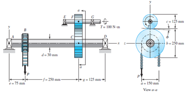
3-77* A torque T = 100 N · m is applied to the shaft EFG. which is running at constant speed and contains gear F. Gear F transmits torque to shaft ABCD through gear C, which drives the chain sprocket at B. transmitting a force P as shown. Sprocket B. gear C. and gear F have pitch diameters of a = 150. b = 250. and c = 125 mm. respectively. The contact force between the gears is transmitted through the pressure angle ϕ = 20°. Assuming no frictional losses and considering the bearings at A, D, E, and G to be simple supports, locate the point on shaft ABCD that contains the maximum tensile bending and maximum torsional shear stresses. Combine these stresses and determine the maximum principal normal and shear stresses in the shaft.
Want to see the full answer?
Check out a sample textbook solution
Chapter 6 Solutions
CONNECT F/SHIGLEY'S MECH.ENGR.DESIGN>I<


- Two sections of steel drill pipe, joined by bolted flange plates at Ä are being tested to assess the adequacy of both the pipes. In the test, the pipe structure is fixed at A, a concentrated torque of 500 kN - m is applied at x = 0.5 m, and uniformly distributed torque intensity t1= 250 kN m/m is applied on pipe BC. Both pipes have the same inner diameter = 200 mm. Pipe AB has thickness tAB=15 mm, while pipe BC has thickness TBC= 12 mm. Find the maximum shear stress and maximum twist of the pipe and their locations along the pipe. Assume G = 75 GPa.arrow_forwardA tubular shaft being designed for use on a construction site must transmit 120 kW at 1,75 Hz, The inside diameter of the shaft is to be one-half of the outside diameter. If the allowable shear stress in the shaft is 45 MPa, what is the minimum required outside diameter d?arrow_forwardA crank arm consists of a solid segment of length bxand diameter rf, a segment of length bltand a segment of length byas shown in the figure. Two loads P act as shown: one parallel to — vand another parallel to —y. Each load P equals 1.2 kN. The crankshaft dimensions are A] = 75 mm, fr> = 125 mm, and b3= 35 mm. The diameter of the upper shaft isd = 22 mm, (a) Determine the maximum tensile, compressive, and shear stresses at point A, which is located on the surface of the shaft at the z axis. (b) Determine the maximum tensile, compressive, and shear stresses at point B, which is located on the surface of the shaft at the y axisarrow_forward
- The figure shows a section of a shaft made of annealed steel with yield strength of 600 MPa and ultimate tensile strength of 700 MPa. Diameters of the shaft are D=30 mm and d=20 mm. Fillet radius of the shoulder section is 2.5 mm. The shaft is rotating and subjected to steady bending moment of M=51 Nm, steady torsion of T=58 Nm and steady axial load of F=14 kN. The operating temperature of the shaft is 20 ᵒC and reliability is 99%. The shaft has ground surface.Calculate the mean component of the shear stress (in MPa)arrow_forwardThe figure shows a section of a shaft made of annealed steel with yield strength of 600 MPa and ultimate tensile strength of 700 MPa. Diameters of the shaft are D=30 mm and d=20 mm. Fillet radius of the shoulder section is 2.5 mm. The shaft is rotating and subjected to steady bending moment of M=51 Nm, steady torsion of T=58 Nm and steady axial load of F=14 kN. The operating temperature of the shaft is 20 ᵒC and reliability is 99%. The shaft has ground surface. Calculate the alternating component of the normal stress (in MPa). (If there is no alternating component of the normal stress, enter "0" in the answer box)arrow_forwardThe shaft in the figure is mounted with a gear wheel key. Shaft material 42CrMo4 The weight of the gear on the shaft is 0.9 kg, dimension, surface and notch factors KbK / Kç = 0.83, shaft speed n = 1120 rpm, shaft transmitted power 7.5 kW, force on shaft Fn = F = 2680 N Since the desired safety coefficient is Ssafe = 2; Check the safety of the shaftarrow_forward
- The cold-drawn AISI 1040 Q&T at 205 ◦C steel bar shown in the figure is subjected to a completely reversed axial load fluctuating between 28 kN in compression to 28 kN in tension. Estimate the fatigue factor of safety based on achieving infinite life, and the yielding factor of safety for the following cases. If infinite life is not predicted, estimate the number of cycles to failure.a) for the part given in Fig 2(a) and b) for the part given in Fig. 2 (b) using the same dimensions (W=25mm, r=3mm, the thickness of 10 mm)arrow_forwardA Steel shaft is subjected to an end thrust producing a stress of 90 MPa and the minimum shearing stress on the surface arising from torsion is 60 MPa .The yield point stress of the material in simple tension was found to be 300 MPa. calculate the factor of safety of the shaft according to the following theory 1)maximum shear stress theoryarrow_forwardA brass shaft AC (G =5.6 *10^3 ksi) is subjected to torsional loads at sections B and C, as shown in Fig. P4.5-2. The outside diameter of the shaft is d1 = do2 =d = 1.25 in. A central hole of diameter di2 = 0.75 in. has been drilled from C to B, creating a two-segment shaft with lengths L1 = L2 =10 in. If the two applied torques are TB = 400 lb in. and TC =200 lb in., respectively, (a) determine the maximum shear stress in the two-segment shaft, and (b) determine the angle of rotation fC (in radians) at the end of the shaft. (Note that both torque TB and TC are pos- itive, meaning that both torques act in the sense shown in Fig. P4.5-2.)arrow_forward
- A rotating shaft of 40×4 mm AISI 1018 cold-drawn steel tubing has a 6 mm diameter hole drilled transversely through it. Estimate the factor of safety guarding against fatigue and static failures using the Gerber and Langer failure criteria for the following loading conditions: a. The shaft is subjected to a completely reversed torque of 120 N.m in phase with a completely reversed bending moment of 150 N.m. b. The shaft is subjected to a pulsating torque fluctuating from 20 to 160 N.m and as steady bending moment of 150 N.m.arrow_forwardA shaft supported between two bearings 750 mm apart, receives 12.5 kW power at 300 rpm through a coupling located to the left of left-hand bearing. It transmits the power to a belt pulley of weight 300 N and diameter 450 mm, which is located at 200 mm to the right of right-hand bearing. The ratio of belt tensions of tight and slack sides is 2:1. The belt tensions act in vertically downward direction. The shaft material has a yield strength of 300 MP & an ultimate tensile strength of 550 MPa . The combined shock & fatigue factor for bending & torsion are 1.5 & 1 respectively. Determine the shaft diameter using ASME code.arrow_forwardThe cold-drawn AISI 1040 steel bar shown in the figure is subjected to an axial load fluctuating between 0kN and 28kN. Estimate the fatigue factor of safety based on achieving infinite life using modified Goodman criterion and the yielding factor of safety. If infinite life is not predicted, estimate the number of cycles to failure.arrow_forward
 Mechanics of Materials (MindTap Course List)Mechanical EngineeringISBN:9781337093347Author:Barry J. Goodno, James M. GerePublisher:Cengage Learning