
Concept explainers
Videos
6–37* to
6–46* For the problem specified in the table, build upon the results of the original problem to determine the minimum factor of safety for fatigue based on infinite life, using the modified Goodman criterion. The shaft rotates at a constant speed, has a constant diameter, and is made from cold-drawn AISI 1018 steel.
| Problem Number | Original Problem, Page Number |
| 6–37* | 3–68, 151 |
| 6–38* | 3–69, 151 |
| 6–39* | 3–70, 151 |
| 6–40* | 3–71, 151 |
| 6–41* | 3–72, 152 |
| 6–42* | 3–73, 152 |
| 6–43* | 3–74, 152 |
| 6–44* | 3–76, 153 |
| 6–45* | 3–77, 153 |
| 6–46* | 3–79, 153 |
Problem 3–70*
Dimensions in inches.
The minimum factor of safety for fatigue on infinite life, using the modified Goodman criterion.
Answer to Problem 39P
The minimum factor of safety for fatigue on infinite life is
Explanation of Solution
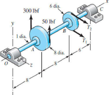
The Free body diagram of pulley
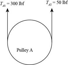
Figure-(1)
The free body diagram of pulley
Figure-(2)
The given assumption is that the belt tension on the loose side at
Write the relationship between tensions on the loose side with respect to tension on the tight side.
Here, the tension on the tight side is
Write the equation to balance the tension on the counter shaft.
Here, the tension on the tight side of pulley
Substitute
Calculate the tension on the loose side.
Write the magnitude of bearing reaction force at
Here, the magnitude of the bearing force at
Write the magnitude of bearing reaction force at
Write the magnitude of bearing reaction force at
Here, the magnitude of bearing force at
Write the magnitude of bearing force at
Here, the magnitude of bearing reaction force at
Calculate the bearing reaction force at
Here, the bearing reaction force at
Calculate the bearing reaction force at
Here, the bearing reaction force at
Calculate the shear force at in
Here, the shear force at
Calculate the moment at
Here, the moment at
Calculate the moment at in
Here, the moment at
The calculations for shear force and bending moment diagram in
Calculate the shear force at
Here, the shear force at
Calculate the moment at
Here, the moment at
Calculate the moment at
Here, the moment at
Write the net moment at
Here, the net moment at
Write the net moment at
Here, the net moment at
Write the torque transmitted by shaft from
Here, the torque transmitted by shaft from
Calculate the bending stress.
Here, the bending stress is
Calculate the shear stress.
Here, the shear stress is
Write the expression for von Mises stress for alternating
Here, alternating stress due to completely reversed is
Write the expression for von Mises stress for mid-range.
Here, mean stress due to completely reversed is
Write the expression for von Mises for maximum stress.
Write the expression for yielding by using distortion energy theory.
Here the
Write the expression for endurance limit of rotary test specimen.
Write the expression for surface condition modification factor.
Write the expression for size modification factor.
Write the expression for modified endurance limit.
Write the expression to find out factor of safety by using modified Goodman.
Here modified endurance limit is
Conclusion:
Substitute
Substitute
Substitute
Substitute
Substitute
Substitute
Substitute
Substitute
Substitute
Substitute
Substitute
Substitute
Substitute
Substitute
Substitute
Substitute
Since
Substitute
Substitute
Substitute
Substitute
Substitute
Substitute
Substitute
Substitute
Substitute
Substitute
Substitute
Substitute
Thus the minimum factor of safety by using modified Goodman criterion is
Want to see more full solutions like this?
Chapter 6 Solutions
CONNECT F/SHIGLEY'S MECH.ENGR.DESIGN>I<


- A motor driving a solid circular steel shaft with diameter d = 1.5 in, transmits 50 hp to a gear at B, The allowable shear stress in the steel is 6000 psi. Calculate the required speed of rotation (number of revolutions per minute) so that the shear stress in the shaft does not exceed the allowable limit.arrow_forwardThree round, copper alloy bars having the same length L but different shapes are shown, in the figure. The first bar has a diameter d over its entire length, the second has a diameter d over one-fifth of its length, and the third has a diameter d over one-fifteenth of its length. Elsewhere, the second and third bars have a diameter Id. All three bars are subjected to the same axial load P. Use the following numerical data: P = 1400 kN, L = 5m,d= 80 mm, E= 110 GPa. and v = 0.33. (a) Find the change in length of each bar. (b) Find the change in volume of each bar.arrow_forwardA Steel shaft is subjected to an end thrust producing a stress of 90 MPa and the minimum shearing stress on the surface arising from torsion is 60 MPa .The yield point stress of the material in simple tension was found to be 300 MPa. calculate the factor of safety of the shaft according to the following theory 1)maximum shear stress theoryarrow_forward
- A screw clamp shown in the figure has a handle with diameter 5 mm made of cold-drawn AISI 1006 steel (table E18 - page 1195). The overall length of the hand is 75 mm. The screw is M 12 coarse (table 8-1) and is 145 mm long, overall. Distance A is 50 mm. The clamp will accommodate parts up to 105 mm high.a) What is the value of screw torque that causes the handle to bend permanently?b) If the collar friction is neglected and if the thread friction is 0.075, what is the screw force value that causes the handle to bend permanently?c) What is the value of clamping force, which will cause the screw to buckle?d) Are there any other stresses or possible failures to be checked?e) If yes, calculate them.arrow_forwardProduced from xCy steel material by machining method, the shaft is bedded at C and D points. With the shaft, constant Fy= 820 N forces in the vertical direction and constant Fx= 4,2 kN forces in the axial direction, which do not rotate together. The tensile strength of the shaft material is (sigma)tensile = (sigma)ut = 620 MPa and the yield strength is (sigma)yield = 420 MPa. For 50% reliability, analyze the fatigue damage condition of the shaft sections A and B separately.arrow_forwardA bar AISI 1035 steel forged and heat treated with minimum yield strength of 570MPa is subjected to bending moment of 290Nm and a torsional moment of 310Nm. Assuming a factor of safety of 2, determine the diameter of rod using the following theories of failure (i) Maximum Shear stress theory and (ii) Distortion Energy theory (iii) Maximum stress theory, also specify which diameter is considered as safearrow_forward
- A helical compression spring is made of a specialty alloy wire with a wire diameter d = 4 mm and an inner coil diameter Di = 18 mm. For this type of alloy and specified wire diameter, the shear yield strength is 715 MPa and the modulus of rigidity is 77.2 GPa. If the spring has 9 active coils, determine the factor of safety nd when the spring deflection is 7 mm.arrow_forwardAn input shaft of a gearbox with motor power P = 7 kW and rotation number n = 1300 rpm. The diameter of an input shaft is d = 20 mm and its material is 16MnCr5. A force of F = 2800 N forces the shaft due to the operation of a gear wheel connected with a wedge on the input shaft. The distances of the gear from the bearings are given as L₁ = 40 mm and L2 = 60 mm. In the most dangerous section, you are required to check the strength according to the S = 3 safety factor. If the section is unsafe in terms of strength, what changes would you make in the design to make it safe? (The surface of the spindle is machined as fine chips, reliability poor Kg = 1.).arrow_forwardThe shaft shown in the figure is machined from AISI 1040 CD steel. The shaft rotates at 1600 rpm and is supported in rolling bearings at A and B. The applied forces are F1 = 1600 lbf and F2 = 640 lbf. A steady torque of 1600 lbf·in is being transmitted through the shaft between the points of application of the forces. ——————————————- Determine the endurance limit for this material as well as the value after correction for surface finish, sizing, and loading. (You must provide an answer before moving to the next part.) The endurance limit for this material is kpsi. The value after correction for surface finish, sizing, and loading is kpsi.arrow_forward
- A certain steel shafting material has an ultimate strength of 93 ksi, a notch radius of 0.25 inch, and a stress concentration factor of 2.5 at its pitch. Determine the fatigue-strength reduction factor for a life of 166,077 cycles onlyarrow_forwardThe shaft in the figure is mounted with a gear wheel key. Shaft material 42CrMo4 The weight of the gear on the shaft is 0.9 kg, dimension, surface and notch factors KbK / Kç = 0.83, shaft speed n = 1120 rpm, shaft transmitted power 7.5 kW, force on shaft Fn = F = 2680 N Since the desired safety coefficient is Ssafe = 2; Check the safety of the shaftarrow_forwardA rotating shaft of 40×4 mm AISI 1018 cold-drawn steel tubing has a 6 mm diameter hole drilled transversely through it. Estimate the factor of safety guarding against fatigue and static failures using the Gerber and Langer failure criteria for the following loading conditions: a. The shaft is subjected to a completely reversed torque of 120 N.m in phase with a completely reversed bending moment of 150 N.m. b. The shaft is subjected to a pulsating torque fluctuating from 20 to 160 N.m and as steady bending moment of 150 N.m.arrow_forward
 Mechanics of Materials (MindTap Course List)Mechanical EngineeringISBN:9781337093347Author:Barry J. Goodno, James M. GerePublisher:Cengage Learning