
Concept explainers
Videos
| Problem Number | Original Problem, Page Number |
| 6–37* | 3–68, 151 |
| 6–38* | 3–69, 151 |
| 6–39* | 3–70, 151 |
| 6–40* | 3–71, 151 |
| 6–41* | 3–72, 152 |
| 6–42* | 3–73, 152 |
| 6–43* | 3–74, 152 |
| 6–44* | 3–76, 153 |
| 6–45* | 3–77, 153 |
| 6–46* | 3–79, 153 |
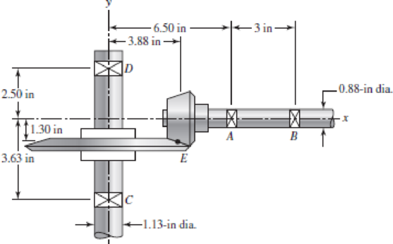
Repeat the analysis of Prob. 3–74 for shaft AB. Assume that bearing A carries the thrust load.
3–74* In the figure, shaft AB transmits power to shaft CD through a set of bevel gears contacting at point E. The contact force at E on the gear of shaft CD is determined to be (FE)CD = ‒92.8i ‒ 362.8j + 808.0k lbf. For shaft CD: (a) draw a free-body diagram and determine the reactions at C and D assuming simple supports (assume also that bearing C carries the thrust load), (b) draw the shear-force and bending-moment diagrams, (c) for the critical stress element, determine the torsional shear stress, the bending stress, and the axial stress, and (d) for the critical stress element, determine the principal stresses and the maximum shear stress.
Want to see the full answer?
Check out a sample textbook solution
Chapter 6 Solutions
CONNECT F/SHIGLEY'S MECH.ENGR.DESIGN>I<


- Three round, copper alloy bars having the same length L but different shapes are shown, in the figure. The first bar has a diameter d over its entire length, the second has a diameter d over one-fifth of its length, and the third has a diameter d over one-fifteenth of its length. Elsewhere, the second and third bars have a diameter Id. All three bars are subjected to the same axial load P. Use the following numerical data: P = 1400 kN, L = 5m,d= 80 mm, E= 110 GPa. and v = 0.33. (a) Find the change in length of each bar. (b) Find the change in volume of each bar.arrow_forwardA tubular shaft being designed for use on a construction site must transmit 120 kW at 1,75 Hz, The inside diameter of the shaft is to be one-half of the outside diameter. If the allowable shear stress in the shaft is 45 MPa, what is the minimum required outside diameter d?arrow_forwardCompare the angle of twist 1 for a thin-walled circular tube (see figure) calculated from the approximate theory for thin-walled bars with the angle of twist 2 calculated from the exact theory of torsion for circular bars, Express the ratio 12terms of the non-dimensional ratio ß = r/t. Calculate the ratio of angles of twist for ß = 5, 10, and 20. What conclusion about the accuracy of the approximate theory do you draw from these results?arrow_forward
- Repeat Problem 2.3-4, but now include the weight of the bar. Sec Table 1.1 in Appendix I for the weight density of steel.arrow_forwardRepeat Problem 11.2-3 assuming that R= 10 kN · m/rad and L = 2 m.arrow_forwardA crank arm consists of a solid segment of length bxand diameter rf, a segment of length bltand a segment of length byas shown in the figure. Two loads P act as shown: one parallel to — vand another parallel to —y. Each load P equals 1.2 kN. The crankshaft dimensions are A] = 75 mm, fr> = 125 mm, and b3= 35 mm. The diameter of the upper shaft isd = 22 mm, (a) Determine the maximum tensile, compressive, and shear stresses at point A, which is located on the surface of the shaft at the z axis. (b) Determine the maximum tensile, compressive, and shear stresses at point B, which is located on the surface of the shaft at the y axisarrow_forward
- What is the maximum power that can be delivered by a hollow propeller shaft (outside diameter 50 mm, inside diameter 40 mm, and shear modulus of elasticity 80 GPa) turning at 600 rpm if the allowable shear stress is 100 MPa and the allowable rate of twist is 3.0°/m?arrow_forwardA polyethylene tube (length L) has a cap that when installed compresses a spring (with under-formed length L1) by an amount ?? = (L1 = L). Ignore deformations of the cap and base. Use the force at the base of the spring as the redundant. Use numerical properties given in the boxes. (a) What is the resulting Force-in the spring, Fk? (b) What is the resulting Force in the tube, Ftl (c) What is the filial length of the tube, Lf? (d) What temperature change ?T inside the tube will result in zero force in the springarrow_forwardSolve the preceding problem if the thickness of the steel plate is. t = 12 mm. the gage readings are x = 530 × 10-6 (elongation) and y = -210 -× l0-6 (shortening), the modulus is E = 200 GPa, and Poisson’s ratio is v = 0.30.arrow_forward
 Mechanics of Materials (MindTap Course List)Mechanical EngineeringISBN:9781337093347Author:Barry J. Goodno, James M. GerePublisher:Cengage Learning