
Microelectronics: Circuit Analysis and Design
4th Edition
ISBN: 9780073380643
Author: Donald A. Neamen
Publisher: McGraw-Hill Companies, The
expand_more
expand_more
format_list_bulleted
Videos
Textbook Question
Chapter 7, Problem 7.10P
(a) Determine the transfer function corresponding to the Bode plot of themagnitude shown in Figure P7.10. (b) What is the actual gain at(i)
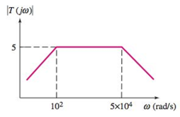
Figure P7.10
Expert Solution & Answer
Want to see the full answer?
Check out a sample textbook solution
Students have asked these similar questions
Sketch the Nyquist Diagram and the Bode Plot of the
transfer function
Give the spectrum?
Find the value of the signal bandwidth using the following bandwidth definition:
1- Half power bandwidth?
2- Noise equivalent bandwidth?
3- Null-to-null bandwidth?
4- 99% of power bandwidth?
3. Given a pass-band amplifier in 66MHz, design a frequency mixer that receives a 199.25 MHz signal and produce a 67.25 MHz signal
Chapter 7 Solutions
Microelectronics: Circuit Analysis and Design
Ch. 7 - (a) For the circuit shown in Figure 7.2, the...Ch. 7 - The circuit shown in Figure 7.10 has parameters of...Ch. 7 - For the equivalent circuit shown in Figure 7.13,...Ch. 7 - The equivalent circuit in Figure 7.14 has circuit...Ch. 7 - The parameters in the circuit shown in Figure 7.15...Ch. 7 - For the circuit shown in Figure 7.2 1(a), the...Ch. 7 - Consider the circuit shown in Figure 7.22(a). The...Ch. 7 - For the emitterfollower circuit shown in Figure...Ch. 7 - The circuit shown in Figure 7.27(a) has parameters...Ch. 7 - Consider the common-base circuit shown in Figure...
Ch. 7 - The commonemitter circuit shown in Figure 7.34...Ch. 7 - A bipolar transistor has parameters o=120 ,...Ch. 7 - Prob. 7.9EPCh. 7 - For the circuit in Figure 7.41(a), the parameters...Ch. 7 - A bipolar transistor is biased at ICQ=120A and its...Ch. 7 - For the transistor described in Example 7.9 and...Ch. 7 - The parameters of a bipolar transistor are: o=150...Ch. 7 - The parameters of an nchannel MOSFET are...Ch. 7 - For the circuit in Figure 7.55, the transistor...Ch. 7 - An nchannel MOSFET has parameters Kn=0.4mA/V2 ,...Ch. 7 - An nchannel MOSFET has a unitygain bandwidth of...Ch. 7 - For a MOSFET, assume that gm=1.2mA/V . The basic...Ch. 7 - The transistor in the circuit in Figure 7.60 has...Ch. 7 - Consider the commonbase circuit in Figure 7.64....Ch. 7 - The cascode circuit in Figure 7.65 has parameters...Ch. 7 - Prob. 7.12TYUCh. 7 - For the circuit in Figure 7.72, the transistor...Ch. 7 - Describe the general frequency response of an...Ch. 7 - Describe the general characteristics of the...Ch. 7 - Describe what is meant by a system transfer...Ch. 7 - What is the criterion that defines a corner, or...Ch. 7 - Describe what is meant by the phase of the...Ch. 7 - Describe the time constant technique for...Ch. 7 - Describe the general frequency response of a...Ch. 7 - Sketch the expanded hybrid model of the BJT.Ch. 7 - Prob. 9RQCh. 7 - Prob. 10RQCh. 7 - Prob. 11RQCh. 7 - Sketch the expanded smallsignal equivalent circuit...Ch. 7 - Define the cutoff frequency for a MOSFET.Ch. 7 - Prob. 14RQCh. 7 - Why is there not a Miller effect in a commonbase...Ch. 7 - Describe the configuration of a cascode amplifier.Ch. 7 - Why is the bandwidth of a cascode amplifier...Ch. 7 - Why is the bandwidth of the emitterfollower...Ch. 7 - Prob. 7.1PCh. 7 - Prob. 7.2PCh. 7 - Consider the circuit in Figure P7.3. (a) Derive...Ch. 7 - Consider the circuit in Figure P7.4 with a signal...Ch. 7 - Consider the circuit shown in Figure P7.5. (a)...Ch. 7 - A voltage transfer function is given by...Ch. 7 - Sketch the Bode magnitude plots for the following...Ch. 7 - (a) Determine the transfer function corresponding...Ch. 7 - Consider the circuit shown in Figure 7.15 with...Ch. 7 - For the circuit shown in Figure P7.12, the...Ch. 7 - The circuit shown in Figure 7.10 has parameters...Ch. 7 - The transistor shown in Figure P7.14 has...Ch. 7 - Consider the circuit shown in Figure P7.15. The...Ch. 7 - The transistor in the circuit shown in Figure...Ch. 7 - For the common-emitter circuit in Figure P7.17,...Ch. 7 - The transistor in the circuit in Figure P7.20 has...Ch. 7 - For the circuit in Figure P7.21, the transistor...Ch. 7 - (a) For the circuit shown in Figure P7.22, write...Ch. 7 - Consider the circuit shown in Figure P7.23. (a)...Ch. 7 - The parameters of the transistor in the circuit in...Ch. 7 - A capacitor is placed in parallel with RL in the...Ch. 7 - The parameters of the transistor in the circuit in...Ch. 7 - Prob. D7.27PCh. 7 - The circuit in Figure P7.28 is a simple output...Ch. 7 - Reconsider the circuit in Figure P728. The...Ch. 7 - Consider the circuit shown in Figure P7.32. The...Ch. 7 - The commonemitter circuit in Figure P7.35 has an...Ch. 7 - Consider the commonbase circuit in Figure 7.33 in...Ch. 7 - Prob. 7.39PCh. 7 - The parameters of the transistor in the circuit in...Ch. 7 - In the commonsource amplifier in Figure 7.25(a) in...Ch. 7 - A bipolar transistor has fT=4GHz , o=120 , and...Ch. 7 - A highfrequency bipolar transistor is biased at...Ch. 7 - (a) The frequency fT of a bipolar transistor is...Ch. 7 - The circuit in Figure P7.48 is a hybrid ...Ch. 7 - Consider the circuit in Figure P7.49. Calculate...Ch. 7 - A common-emitter equivalent circuit is shown in...Ch. 7 - For the common-emitter circuit in Figure 7.41(a)...Ch. 7 - For the commonemitter circuit in Figure P7.52,...Ch. 7 - Consider the circuit in Figure P7.52. The resistor...Ch. 7 - The parameters of the circuit shown in Figure...Ch. 7 - The parameters of an nchannel MOSFET are kn=80A/V2...Ch. 7 - Find fT for a MOSFET biased at IDQ=120A and...Ch. 7 - Fill in the missing parameter values in the...Ch. 7 - (a) An nchannel MOSFET has an electron mobility of...Ch. 7 - A commonsource equivalent circuit is shown in...Ch. 7 - Prob. 7.60PCh. 7 - The parameters of an ideal nchannel MOSFET are...Ch. 7 - Figure P7.62 shows the highfrequency equivalent...Ch. 7 - For the FET circuit in Figure P7.63, the...Ch. 7 - The midband voltage gain of a commonsource MOSFET...Ch. 7 - Prob. 7.65PCh. 7 - Prob. 7.67PCh. 7 - The bias voltages of the circuit shown in Figure...Ch. 7 - For the PMOS commonsource circuit shown in Figure...Ch. 7 - In the commonbase circuit shown in Figure P7.70,...Ch. 7 - Repeat Problem 7.70 for the commonbase circuit in...Ch. 7 - In the commongate circuit in Figure P7.72, the...
Knowledge Booster


Learn more about
Need a deep-dive on the concept behind this application? Look no further. Learn more about this topic, electrical-engineering and related others by exploring similar questions and additional content below.Similar questions
- What is the voltage gain (Av) of the circuit when β = 100, r0 = 40 kΩ, RB = 360 kΩ, RC = 3.3 kΩ, RE = 220 Ω, Rs = 15 kΩ and RL = 248 kω in the circuit given in the figure?Note-1: the output impedance of the transistor r0 will be taken into account in calculations.Note-2: capacitors are negligible at midband frequency.arrow_forwardDetermine the magnitude of frequency transfer function of the system shown below:arrow_forwardAnswer the Following and provide solution. 1. The maximum frequency deviation of the carrier is ± 15 kHz and the maximum modulating frequency is 3 kHz, calculate for the modulation index. 2. Assume that the 60-dB bandwidth of a receiver is 12 kHz and the 6-dB bandwidth is 7 kHz. What is the shape factor of the circuit? 3. What is the bandwidth of a receiver with a quality factor of 50 and a resonance frequency of 540 kHz. 4. What is the maximum bandwidth of an FM signal with a deviation of 27 kHz and a maximum modulating signal of 4 kHz as determined by Carson’s rule? 5. A PM signal has a maximum allowed deviation of 17 kHz and an actual deviation of 8 kHz. What is the percentage modulation?arrow_forward
- Tuned Circuit Design Using a VARICAP (a) Refer to the capacitance curves for the Motorola 1N4002 The input tuning circuit of a standard analog FM radio is given below. Specify, that is design for, a voltage, capacitance, and inductance required to tune the circuit to the center frequency of KUMD-FM which operates at 103.3 MHz. Sketching and labeling a representative resonance curve is required to support your calculations. There is no single correct design answer set of values since it depends upon the voltage you initially select to tune your diode.arrow_forwardA. Suppose that a modulated signal x(t) is created by taking a baseband signal and mixing it with a 250 Hz cosine signal, resulting in the passband spectrum X(f) shown below. Suppose that the modulated signal x(t) is mixed with a 200 Hz cosine signal c(t). The spectrum of the 200 Hz cosine is shown below as C(f). (Please look at the picture.) Which of the spectra above is the spectrum of the after mixing x(t) and c(t)? (Please pick among the choices in the picture) ============================================= B. Please look at the 2nd picture. Need help. Thank you.arrow_forwardWhat is a Bode plot?arrow_forward
- A filter is provided with a cascaded differential amplifier. The midband gain and noise coefficient of the filter are given as −3 dB and 3 dB, respectively.According to this,a) If it is known that the amplifier gain is ?1= 20 dB and the noise coefficient is ?1= 2 dB, calculate the midband gain for the entire cascaded system. Give your answers in dBarrow_forwardClassify the following carriers waves into either transmitter or receiver. Thank you!- oscillator, - receiver antenna,- broadcast antenna, - modulator,- amplifier,- microphone- loudspeaker,- amplifier,- demodulator- tuner,arrow_forwardWhat are the relative amplitudes of the fourth pair of sidebands for an FM signal with a deviation ratio of 8?arrow_forward
- What is the coherent bandwidth equation?arrow_forwardChose the correct answer 6- The bandwidth required for a modulated carrier depends on: a) The carrier frequency b) the signal-to-noise ratio c) the signal-plus-noise to noise ratio d) The baseband frequency rangearrow_forwardA power spectral density has a completely flat shape over the bandwidth of the system, which is 0 to 4kHz. Find the proportion of the signal’s power that that lies in the region that is in EXCESS of 3.4 kHz.arrow_forward
arrow_back_ios
SEE MORE QUESTIONS
arrow_forward_ios
Recommended textbooks for you
 Introductory Circuit Analysis (13th Edition)Electrical EngineeringISBN:9780133923605Author:Robert L. BoylestadPublisher:PEARSON
 Delmar's Standard Textbook Of ElectricityElectrical EngineeringISBN:9781337900348Author:Stephen L. HermanPublisher:Cengage Learning
 Programmable Logic ControllersElectrical EngineeringISBN:9780073373843Author:Frank D. PetruzellaPublisher:McGraw-Hill Education
 Fundamentals of Electric CircuitsElectrical EngineeringISBN:9780078028229Author:Charles K Alexander, Matthew SadikuPublisher:McGraw-Hill Education
 Electric Circuits. (11th Edition)Electrical EngineeringISBN:9780134746968Author:James W. Nilsson, Susan RiedelPublisher:PEARSON
 Engineering ElectromagneticsElectrical EngineeringISBN:9780078028151Author:Hayt, William H. (william Hart), Jr, BUCK, John A.Publisher:Mcgraw-hill Education,
Introductory Circuit Analysis (13th Edition)
Electrical Engineering
ISBN:9780133923605
Author:Robert L. Boylestad
Publisher:PEARSON
Delmar's Standard Textbook Of Electricity
Electrical Engineering
ISBN:9781337900348
Author:Stephen L. Herman
Publisher:Cengage Learning
Programmable Logic Controllers
Electrical Engineering
ISBN:9780073373843
Author:Frank D. Petruzella
Publisher:McGraw-Hill Education
Fundamentals of Electric Circuits
Electrical Engineering
ISBN:9780078028229
Author:Charles K Alexander, Matthew Sadiku
Publisher:McGraw-Hill Education
Electric Circuits. (11th Edition)
Electrical Engineering
ISBN:9780134746968
Author:James W. Nilsson, Susan Riedel
Publisher:PEARSON
Engineering Electromagnetics
Electrical Engineering
ISBN:9780078028151
Author:Hayt, William H. (william Hart), Jr, BUCK, John A.
Publisher:Mcgraw-hill Education,
Why Use Bode Plots? | Understanding Bode Plots, Part 1; Author: MATLAB;https://www.youtube.com/watch?v=F6-EaZobHNk;License: Standard Youtube License