
Videos
Consider the circuit shown in Figure P7.23. (a) Write the transfer function
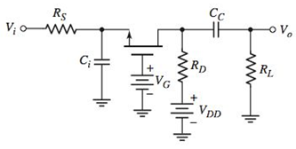
Figure P7.23
a.
The transfer function
Answer to Problem 7.23P
The expression for transfer function of the circuit is,
Explanation of Solution
Given:
The circuit is given as:

Calculation:
Refer to the given circuit:
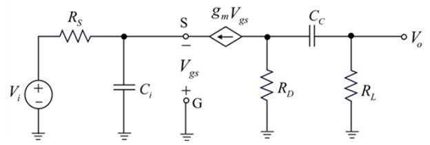
Drawing the small signal equivalent circuit using the simplified hybrid
Now drawing the frequency domain equivalent circuit of above figure:
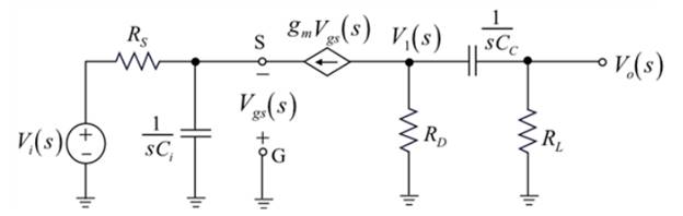
Applying the nodal analysis to derive the expression for
Solving the above equation:
Applying the Kirchhoff s current law at node
Applying the Kirchhoff s current law at output node:
Evaluating the expression for
Substituting
The expression for transfer function of the circuit is given as:
Solving the above equation:
So,
Therefore, the expression for transfer function of the circuit is,
b.
The expression for the time constant associating with the input portion of the circuit.
Answer to Problem 7.23P
The expression of the time constant associated with the input portion of the circuit:
Explanation of Solution
Given:
The circuit is given as:
Calculation:
Evaluating the expression for the time constant associated with the input portion of the circuit.
From the equation (3) , the time constant associated with the input portion of the circuit is,
Hence, the expression of the time constant associated with the input portion of the circuit .
c.
The expression for the time constant associating with the output portion of the circuit.
Answer to Problem 7.23P
The expression of the time constant associated with the output portion of the circuit:
Explanation of Solution
Given:
The circuit is given as:

Calculation:
Evaluating the expression for the time constant associated with the input portion of the circuit.
From equation (3), the time constant associated with the input portion of the circuit is expressed as:
Therefore, the expression for the time constant associated with the output portion of the circuit:
Want to see more full solutions like this?
Chapter 7 Solutions
Microelectronics: Circuit Analysis and Design


- A carrier is modulated simultaneously by two baseband signals with modulation indices of 0.3 and 0.4 respectively. If the scheme is AM, then what will the overall modulation index?arrow_forwardWhat are the advantages and disadvantages of single-sideband transmission? Briefly describe each.arrow_forwardWhat is the coherent bandwidth equation?arrow_forward
- A. How many numbers of constellation points exist in phase for 3bit ASK? B. What happens to the radio wave propagation when the frequency is below critical angle? C. If the mark frequency and space frequency are same then what happens to FSK? D. What is the Carson’s rule? E. What is the Maximum data rate in a minimum channel bandwidth is ? F. What is radio horizon and where is it used? G. What are the phase angle limitations of a BPSK? H. What is the change in channel capacity when two number of bits are increased?arrow_forwardIdentify how the excessive bandwidth use of FM can be overcome. (Check all that apply.) By using narrowband FM with small deviation ratios By using wideband FM with large deviation ratios By operating in the ultrahigh frequency (UHF) region By operating in the ultralow frequency (ULF) region By operating in the microwave regionarrow_forwardIt is given as ?1 = ?3 = 50Ω and ?2 = 25Ω in the two-gate Π circuit given in the figure. According to this,a) Find the scattering matrix of the two-port circuit Π.b) Using the scattering matrix in a), determine the properties provided by the two-port circuit.arrow_forward
- 2 (AM) A 10 V amplitude sinusoidal signal is used as a modulating signal to generate an AM signal with modulation index 0.8. What is the amplitude of the carrier? What is the power of the side bands? What is the efficiency of the modulated signal?arrow_forward5. Why must modulated signals be demodulated?A. To recover the original intelligenceB. To improve the spectral efficiency of digital transmissionsC. To enable implementation of advanced featuresD. To produce one or more significant sideband pairsarrow_forwardWhat is the maximum average output power of a single-sideband signal (SSB) transmitter rated at 250 W peak envelope power (PEP)? Warrow_forward
- Q1 ] A carrier signal ( peak amplitude = 39V , frequency = 100MHz ) frequency modulated by the baseband signal ( peak amplitude = 5V , bandwidth = 12.02kHz ) . The frequency deviation is 77.53kHz , and the load is 5112. Determine ( a ) the load power , ( b ) the bandwidth of the transmitted signal . ( consider only IJn ( $ ) > 0.1 ) .arrow_forward5. The following data is available: fc= carrier frequency = 750kHz, Ac= maximum amplitude of the unmodulated carrier = 10V fm= modulator frequency = 300Hz-8kHz modulation index m=0.5 a) What is the frequency of the upper sideband? b) What is the frequency of the lower sideband? c) What is the amplitude of the modulating signal? d) What is the maximum amplitude of the envelope of the modulated signal? e) What is the minimum amplitude of the envelope of the modulated signal? f) What is the bandwidth of the modulated wave? g) Write an expression for the modulated wavearrow_forward(a) What is the frequency deviation and carrier swing necessary to provide 75% modulation in theFM broadcast band? (b) Repeat for an FM signal serving as audio portion of a TV broadcast.arrow_forward
 Introductory Circuit Analysis (13th Edition)Electrical EngineeringISBN:9780133923605Author:Robert L. BoylestadPublisher:PEARSON
 Delmar's Standard Textbook Of ElectricityElectrical EngineeringISBN:9781337900348Author:Stephen L. HermanPublisher:Cengage Learning
 Programmable Logic ControllersElectrical EngineeringISBN:9780073373843Author:Frank D. PetruzellaPublisher:McGraw-Hill Education
 Fundamentals of Electric CircuitsElectrical EngineeringISBN:9780078028229Author:Charles K Alexander, Matthew SadikuPublisher:McGraw-Hill Education
 Electric Circuits. (11th Edition)Electrical EngineeringISBN:9780134746968Author:James W. Nilsson, Susan RiedelPublisher:PEARSON
 Engineering ElectromagneticsElectrical EngineeringISBN:9780078028151Author:Hayt, William H. (william Hart), Jr, BUCK, John A.Publisher:Mcgraw-hill Education,